Adaptive Meshing in SolidWorks Simulation
By Hawk Ridge Systems
CAD/CAM/CAE CAD Hawk Ridge Systems simulation SolidWorksUnderstand and apply SW Simulation's automatic mesh optimization settings.
Mesh refinement is an important part of effectively using SolidWorks Simulation, and selective mesh refinement help the user receive high quality results without an unnecessarily large time investment during the solving process. One of the tools that can assist in this process is adaptive meshing, which is a tool used to iteratively vary the mesh settings for your model without active user intervention.
SolidWorks Simulation uses two different methods to accomplish this: h-adaptive and p-adaptive meshing. H-adaptive meshing physically adjusts the size of the mesh cell in areas of the model where smaller mesh is needed, while p-adaptive meshing adjusts the polynomial order of the mesh to improve accuracy. This is all done automatically by the software based on a desired accuracy defined by the user. The software achieves the target accuracy by measuring the change in strain energy and stops iterations when two consecutive values differ by less than the given value.
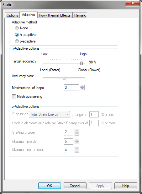
First, where are these tools located and how do we activate them? Adaptive meshing is only available for solid mesh models. The setting to activate it is located in the “Properties” window for your simulation study. To access this menu, right click on the top level icon in your studies’ feature tree and select the “properties” option. Select the “adaptive” tab along the top of the properties window. In the top section of the tab will be the options for “none, h-adaptive, and p-adaptive mesh refinement”.
h-Adaptive
As previously stated, h-adaptive meshing varies the refinement level or density of the mesh. This is done automatically by the software in areas it’s needed without any user interaction. The user can control the process based on the number of iterations and accuracy.
- Target accuracy measures the change in strain energy and stops iterations when the two values differ by less than the stated value; in the provided example of 98%, the iterations would stop when the difference in strain energy between two loops is below 2%
- Accuracy Bias allows the user to balance whether the software iterates to achieve accurate peak stress results in areas where stress concentrations exist, or whether it iterates to achieve accurate global results; with the slider to the far left (Local), areas with stress concentrations will be very highly refined.
- The max number of loops controls the allowable number of iterations.
- Mesh Coarsening allows the software to intelligently loosen or coarsen the mesh in areas that do not need a highly defined mesh
p-Adaptive
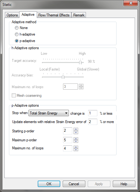
SolidWorks has two main types of tetrahedral mesh elements. Draft quality elements are first order tetrahedral elements and therefore are linear. High quality elements are second order tetrahedral elements and are parabolic in nature. Using a p-Adaptive mesh setting allows the user to take advantage of mesh elements up to the 5th order.
The user has control over the iteration process in a similar fashion to the h-Adaptive method. A value for change in strain energy, von Mises stress, or displacement can be set to control when the iterations stop.
- Update elements with relative strain energy of 2% or more limits iteration to only areas that meet the specified value.
- Starting p-order allows the user to control the starting order of the elements and iteration process.
- Maximum p-order stops the process when a certain order of elements has been reached.
- The max number of loops controls the allowable number of iterations.
Both h-Adaptive and p-Adaptive mesh options can help the user by automatically refining the mesh to achieve more accurate results. These processes are more time consuming than a normal mesh. They are best used for situations in which you are not getting satisfactory results from a standard study or in situations where the accuracy of the result needs to fall within a narrow margin.
For more Flow Simulation and other Solidworks tips, check out HawkRidge Systems Blog


