Automating Inventor part creation with Excel
By Nino Caldarola, Application Engineer, ImaginIT Technologies
CAD/CAM/CAE Autodesk CAD Imaginit Technologies Inventor Nino CaldarolaHow to use Excel to create multiple part (or assembly) variations in AutoCAD Inventor.
The heart and soul of any part are its features. Features are controlled by the use of parameters and these are based on good sketching practices as well as a good understanding of how each interacts with each other.
The manipulation of these vital control elements can be achieved in many ways; however, manipulation from an external source (MS Excel, in particular) can simplify the creation of multiple variations of parts (and assemblies!) when a full functioning configuration system is not required. We’ll be looking at an example of this in the following tutorial:
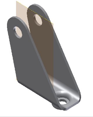
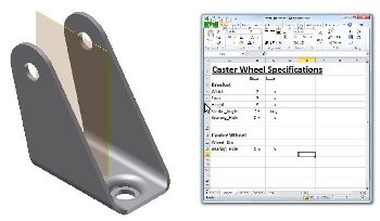
This is an example of a castor bracket. The task is to allow a user (CAD or Non-CAD) to input various values to effect change to the design rather and re-create the design from scratch.
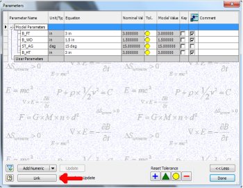
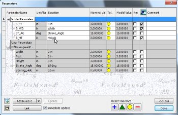
If we look at its parameter list, we observe that it has several of its major parameters renamed for clarity. This is a good practice so as to isolate important features that we’d like to control.
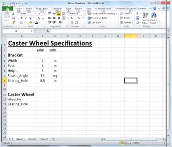
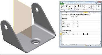
The following is an Excel Sheet, set up to allow us to simply input various values that will be pushed to Inventor to drive the model. The important factors required in the Spreadsheet are:
Name, Value (may be any input that will produce a result: Hard numbers, Formulae, or Cell Mathematics), and Unit of Measure (UoM).
To create the link between the External Source (Excel) and the model, first open the Parameter Manager in Inventor. Click the “LINK” button on the bottom Left Hand Side of the dialog box.
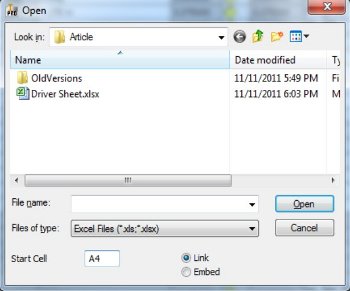
Begin by Browsing for the Spreadsheet. Select the sheet and change the “Start Cell” number to the first cell containing the first variable name.
If you leave the selection as a “Link”, you’ll need to “carry” the spreadsheet with the model (normally in the same directory as the model). However, this option will allow you to change the source spreadsheet, if required.
If you “Embed”, then you will only have access to a particular spreadsheet. If you need to change the source, you’ll need to delete it and relink.
On clicking “Open”, the variables will be placed as “User Parameters”, however, you may only change them from the spreadsheet.
This allows full control of the parameters through the familiar Excel interface and also allows the full power of Excel to be utilized to drive the model in many ways simultaneously.
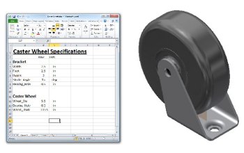
This, however, is not only limited to parts. Assemblies can be driven in the same way. This allows multiple part assemblies to be manipulated from a single source.
By using a single spreadsheet with multiple areas of manipulation, a rudimentary configuration system can be set up to create various models by simply inputting within Excel.
 Nino Caldarola is an Application Engineer, Manufacturing Solutions for ImaginIT Technologies Canada. As a result of teaching CAD for the past fourteen years, Nino is extremely knowledgeable and comfortable in the latest technology and enjoys presenting to audiences in a classroom environment. He has also worked with customers in concept development and prototyping in the mechanical and manufacturing engineering fields. His personal development projects have taken him into the new technologies of rapid prototyping and 3D Print and his ultimate achievements include two models (recognized as the most complex and largest in the world) that have been 3D Print produced and exhibited at Autodesk University 2009 and 2010. Both models are on display at the Autodesk Gallery.

