Clip modeling techniques for rapid manufacturing
By Proto Labs
CAD/CAM/CAE Proto Labs Protomold rapid manufacturing rapid prototypingHow to design clip features for an assembly that needs to snap together.
One of the many benefits of plastic resin is the ease with which it can be molded into complex shapes. This often allows a single part to replace two or more parts made of other materials. Among the complex features that can be molded into a plastic part are a variety of integrated snap connectors, which can also eliminate the need for still more parts, such as screws, or for secondary processes like adhesive bonding.
The first consideration in snap connector design is material. In order for a snap connector to work, some area of the part must flex. This is why snap connectors can work in plastics (though not all plastics) but not in rigid materials like glass or ceramic. Resins that are especially suited for snap-fitted parts include ABS, polycarbonate, unfilled nylon, polypropylene, and other resins with similar properties.
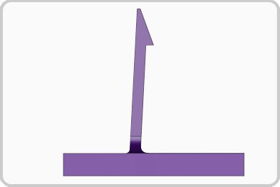
The most familiar type of molded-in connector, the hooked cantilever clip (Figure 1), will be addressed in this design tip. Other connector types, including annular snap fits and torsional snap fits, will be addressed in Part 2 of this design tip next month.

Figure 1: Cantilever clip with 90° hook face
Cantilever clips are used in a variety of applications (e.g., access panels in electrical devices) and can take many forms. Two key questions in designing such clips are:
• Do you want the connection to lock or to release with a pull?
• Do you want it to release at all or to be permanent?
If the clip’s hook face is at 90° to the direction of connection, the connection will lock and cannot be undone by a simple pull (unless you pull hard enough to break the clip). If, however, the latching face of the hook is angled (Figure 2), a simple pull will release the connection.

Figure 2: Cantilever clip with angled hook face to facilitate removal
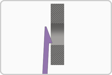
If you want a locking but non-permanent connection, say for an access panel, you can angle the hook face at 90° but allow the hook to be pushed manually out of its slot to unlock the connection. This is simple if the hook is positioned on the outside of the part. If the hook is located behind a wall, the designer can provide a “window” through which the hook can be accessed (Figure 3).

Figure 3: Clip positioned in a “window” to allow unlocking
Design of a cantilever clip determines its effectiveness and durability. The clip’s arm must flex enough to allow it lock and unlock without breaking or deforming. This ability to flex depends on several factors including the material’s Young’s modulus, the angle through which the clip must deflect, determined by the depth of the hook, and the shape and length of the clip’s flexing arm. (Detailed formulae for clip design can be found at efunda.com.) They are also incorporated in many CAD programs, eliminating the need for separate calculation. Finite element programs can also be used to adjust the clip design to avoid breakage. Additional information on clip design can be found in a previous Protomold design tip.
Because the length of the clip’s flexing arm is critical and some designs offer limited space, there are several ways to increase the effective length of the arm.
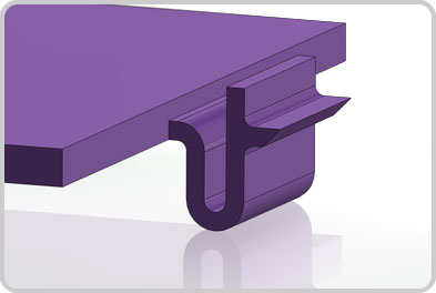
• The arm can be folded into a “u” shape, as is often seen in battery compartment covers (Figure 4).

Figure 4: Clip folded to increase the flexing arm’s effective length in limited space
• The wall from which the arm extends can be notched, making that segment of the wall an extension of the arm.
• The wall from which the arm extends can itself be made flexible, reducing the amount by which the arm must flex.
Because a clip is, by its nature, designed to catch, it can, depending on its orientation, act as an undercut in a two-part mold. There are three ways to deal with this.
• The simplest is to use a sliding shutoff extending through a hole at the base of the clip to form the bottom of the hook and one face of the flexing arm (Figure 5). This allows use of a simple two-part mold.

Figure 5: Clip with hole at the base to allow use of a simple two-part mold
• A side-action cam can form the hook and then withdraw before the mold opens. This is an effective, but more complex approach.
• A pickout can be inserted manually into the mold to form the clip and then manually removed from the finished part and reinserted into the mold for the next cycle. Get more information on pickouts.
Check out part 2 of this tutorial on Proto Labs site. To get more injection mold design tips like this, check out Proto Lab’s website or check out their Design Tips newsletter.
For further tips on clips, check out this Video Design Tip on Spring Clips.
