Editing with Live Sections in Solid Edge
By John Pearson
CAD/CAM/CAE CAD Design Fusion John Pearson Solid EdgeLive Sections make working with synchronous files in a parametric environment more intuitive.
In the Solid Edge synchronous modeling paradigm, you can use the Live Section command to create a 2D cross-section on a plane through a 3D part.
Live sections can make it easier to visualize and edit certain types of parts, such as parts that contain revolved features. You can then edit the 2D elements of the live section to modify 3D model geometry.
Recently we have fielded some questions from customers who have received synchronous models, which they needed to edit. They are still working in the ordered paradigm and have not taken any synchronous training. They wanted to know how they could accurately edit a synchronous part.
For these customers, we often show them how to use the Live Section command. It is similar to working with dimensional sketches and is often easier to visualize than some of the other approaches. Below is such an example:
Scenario: The user has a synchronous roller part for a conveyor mechanism, as shown below.

The user wishes to edit the part to look like the following part.
First, it should be noted that there are several ways to edit this part. But we will illustrate a method using the Live Section command. To create a live section you follow these simple steps:
1. Choose Home tab→Section group→Live Section.
2. Select an existing planar face, reference plane, or principal plane on a coordinate system.
The live section is created.
Tips:
- You can use the Live Section Colors section on the Colors page of the Solid Edge Options dialog box to specify the colors you want to use for the edges, center lines, and regions for live sections.
- You can use PathFinder to display and hide live sections.
- The live section automatically updates when you add or remove features, or modify the 3D model.
- Move the live section plane and the section updates as the plane intersects the model.
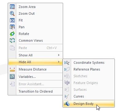
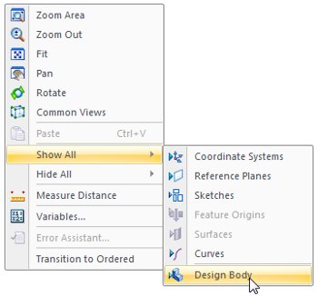
To get a better view of the live section, hide the design body using a RMB click over the display screen, to access the following menu:
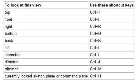
Align the view to give you a top down view of the live section. Below is a list of keyboard shortcuts to help you orient your view.
In this case, we’ll use Ctrl+R to get the top down view of the live section.
Then, use the “Distance Between” command to place the following dimensions.
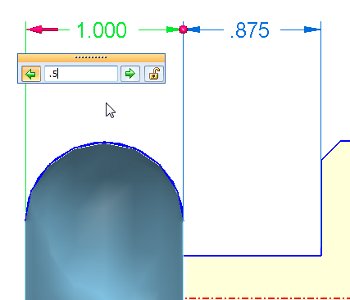
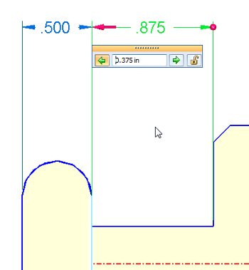
In this scenario, we’ll modify the 1.000” to 0.500” and the 0.875” to 0.375”. First, select the 1.000 dimension. Ensure that the directional (red) arrow is pointing to the side that will move, then type in the 0.500 value.
Before hitting enter, lock the dimension by clicking on the little lock icon. This will prevent the edit to the 0.875 dimension from altering this edit.
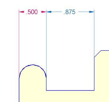
Click “Enter” to accept the dimensional change. Notice that the new value is in red, indicating a locked state.
Live sections are subject to the same live rules as 3D editing. Therefore, since this part is symmetrical about a base plane, I only have to edit the one side and the other side automatically updates.
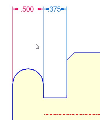
Next I modify the 0.875 dimension to 0.375, again making sure that the directional (red) arrow is pointing to the side that will move.
Since this is the last dimension I will edit here, I won’t lock it.
Once again the symmetric live rule updates the other side automatically.
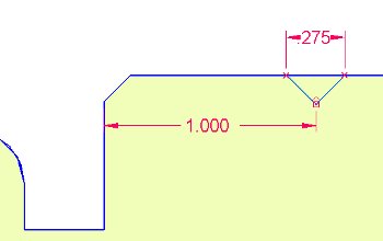
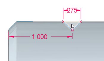
Next, place some cutouts into the roller. Although we’ll do this on the 3D model, you can use the live section to help accurately place the initial cutout sketch, as shown below:
Then show the Design Body and hide the Live Section.
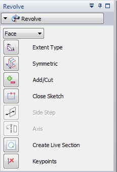
Using the Revolve command, set the selection type to Face and select the sketch region, created by the sketch and the edge of the cylinder.
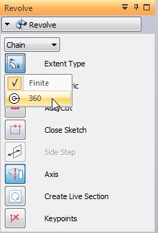
RMB click to accept this selection. Notice the Axis icon activates and you will be prompted to select the axis of revolution.

Move the cursor over the large cylinder and the axis of the cylinder highlights for selection. Select this axis.
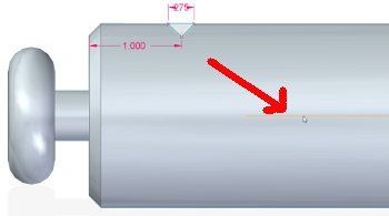
To ensure that this will be a revolved cutout, selecting the remove option.
Next, select a full 360 degree revolution…
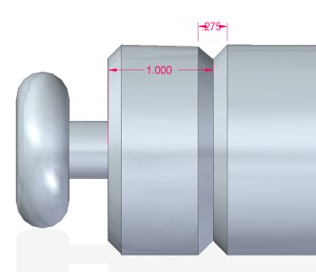
And create the first groove, accurately positioned and dimensioned.
To complete the model, use the Rectangular Pattern command. First, select the newly created Revolved Cutout from the PathFinder.
Then, select the Rectangular Pattern command.
Select the Right(zy) reference plane to place the preview of the pattern.
Note: The synchronous pattern command automatically generates a preview of a default pattern and provides on screen dynamic input boxes for you to enter your desired parameters.
In this scenario, the following values were entered:
- X Count: 14
- Y Count: 1
- X distance of 14”
- Because the Y Count is 1, I don’t have to enter a Y distance.
RMB click to accept the pattern and model is complete.
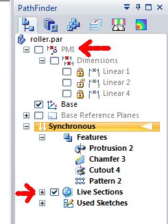
Notice that if the PMI dimensions are hidden and the Live Sections are turned on, the live section will update to include the grooves.
Notice also that, in this scenario, we could have modified this part using just the 3D model and steering wheel to adjust the ends. We could have also just used 3D dimensions directly on the model. However, using the live section provides some users with a comfort level and easier visualization, similar to working in the ordered environment.
It’s also worth mentioning that if this model had been designed in another CAD package, the exact same steps would be used to make the exact same edits. With synchronous technology, the user can take any CAD model and work with it as if it was modeled in Solid Edge.
For additional information, see the topic Live Section command in Solid Edge Help. A training activity for this command is located in the self paced training section. Follow this link www.solidedge.com/spt/en/ST4/spse01520/book.html, and then click on the Working with Live Sections chapter.
 John Pearson is a Senior Technical Trainer and Application Specialist at Designfusion. He has over 24 years’ experience in the CAD/CAM industry, is a Certified Adult Trainer and has taught evening CAD courses at colleges in Ontario. He is also a major contributor of articles on the Design Fusion blog.


