
Picking the Right Linear Positioning Device
By Tony Kliber
Power TransmissionEach technology has its benefits but choosing the proper one avoids common problems.
Linear drive systems have been used for thousands of years, as far back as the ancient Egyptians who used tree trunks to move heavy blocks of stones, providing the precursor to linear motion solutions such as ball screws and roller pinion systems. Today, linear motion technology is used to support, locate, guide and move machinery components in a wide range of applications in the aerospace, machine tool, medical, factory automation, packaging and other industries. While the basic requirements of linear motion technology are to provide load-bearing capability and accurate motion, other requirements are also important in many cases.
The linear drive technology used in a product plays an important role in providing the functionality, performance, durability, energy consumption and other attributes that enable the product to outperform the competition. Engineers can choose from a wide range of linear drive technology choices such as lead screws, ball screws, rack and pinion systems, belt drives, linear motors and roller pinion systems.
It’s critical to carefully consider all of the options to avoid common problems such as low accuracy, backlash/vibrations, high cost, dirty operations, high maintenance, low load capacity, excessive noise, low speed, etc. A systematic selection process can ensure that the chosen linear drive technology matches the requirements of the application. Selecting the right technology can also reduce design complexity, improve performance and reduce the overall cost of assembly.
Lead screws
Lead screws use the helix angle of a thread to convert turning motion into linear motion. The large area of sliding contact between the male and female members of the thread generate relatively high frictional losses. The result is that lead screws are less efficient and not as accurate as ball screws. Lead screws provide relatively high load-carrying capacity although typically less than ball screws. A key advantage of lead screws is low cost – they are typically only 1/10 the cost of equivalent ball screws. Lead screws are available in wide range of lead sizes which means the lead can be selected to provide the right balance of positioning accuracy and speed. Lead screws generally produce very little noise as long as sufficient lubrication is maintained. However, they can be difficult to use in long-distance moves as the screw is typically unsupported between the two ends.
Ball screws
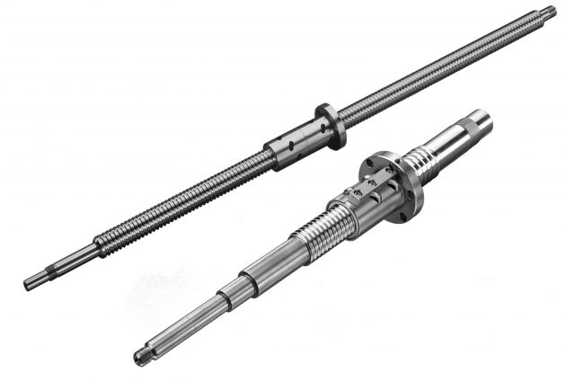 The ball screw drive consists of a ball screw and ball nut with recirculating bearings that roll in the grooves formed by the screw and nut. The ball screw distributes the load over a large number of rolling elements, resulting a high load carrying capability. The use of a large number of precision rolling elements also provides high levels of accuracy. Ball screws also provide low levels of friction which translates into high mechanical efficiency and reduced power requirements. The duty cycle of ball screws is also quite high because they generate relatively low levels of frictional heat. However, compared to other linear drive technologies, ball screws tend to be expensive and they also require that lubrication be maintained to provide reasonable life. Finally, ball screws are prone to noise, primarily caused by ball recirculation.
Belt drive Systems
Belt-drive linear motion systems with ball guides are typically selected when high speeds, high rates of acceleration and long stroke lengths are the most important criteria. Belt-driven, slide guided linear actuators offer somewhat lower speed and acceleration capabilities at a corresponding lower cost. Linear positioning accuracy of belt drives, as might be expected, is not as great as either lead screws or ball screws. The load capacity of both ball-guided and slide-guided belt drives is somewhat lower than ball screws. Belt stretch and stiffness are other drawbacks. Belt-driven linear motion systems are generally capable of high duty cycles since they avoid concerns about frictional heat buildup in the bearing of a lead screw or ball screw. Additional advantages of belt-driven systems include the fact that they generate relatively little noise and require relatively little maintenance.
Chain drives
Chain drives convert rotary motion to linear motion through a series of chain links that mesh with a toothed sprocket and with a linear slide. An advantage of chain drives over belt drives is higher loads because chain drives are metal. Chain drives also take up less space than belt drives and are not prone to damage by oil, grease, sunlight or age. Unlike belt drives, chain drives are also capable of operating in wet conditions. On the other hand, chain drives typically generate more noise and have a greater tendency to vibrate than belt drives. They also provide a lower load capacity and service life than gear drives.
Linear motors
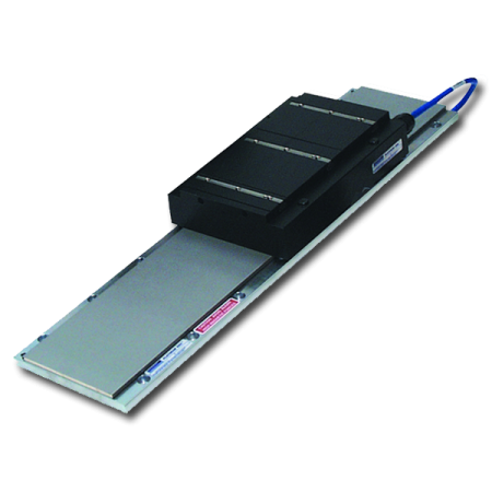 Linear motors are based on the concept of unwrapping a conventional rotary servo motor with the stator becoming a forcer and the rotor transforming into a coil or magnet rail. Linear motors make it possible to achieve direct linear motion without any rotary to linear transmission devices. Brushed linear motors use coils in the linear rail and magnets in the forcer. Brushes in the forcer contact a bar running the length of the motor to provide commutation. Both the windings and forcer are contained within the forcer of a linear step motor. The advantages of linear motors include high speeds, high levels of accuracy and fast response. Their limitations include high cost, large package size and generation of considerable amounts of heat. Linear motors also have a low capacity, similar to the comparison of direct drive motors vs. motors with a gearbox – the direct drive motor has to be significantly larger to get the same capacity.
Rack and pinion sets
Rack and pinion gear sets consist of a circular gear called a pinion that engages the teeth of a linear gear called a rack to convert rotational motion to linear motion. Rack and pinion gears are commonly used as linear actuators in a wide range of machinery. For example, they are used to move the axes of computer numerical control (CNC) machine tools such as machining centers. Helical racks offer quieter running at high speeds and a higher load carrying capacity due to the higher tooth contact ratio. Lubrication is important to ensure long life for rack and pinion sets. The advantages of rack and pinion sets include relatively few components and high levels of accuracy even over long travel lengths. Their disadvantages include their relative high levels of friction. Plus, rack and pinion drives need to run with clearance, so backlash can be a major disadvantage.
Roller pinion systems
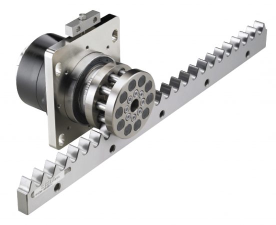 While similar to rack and pinion at first glance, roller pinion systems use bearing-supported rollers, instead of spur gear teeth, to engage the rack teeth. Positioning accuracy of roller pinion systems ranges from 30 to 80 microns. For instance, a given size product in a premium model may deliver positional accuracy of ±30µm, a life expectancy of 30 million cycles/tooth and a maximum dynamic load of 14,000N. For medium loads, a universal model can deliver accuracy of ±50µm for 5 million cycles/tooth and carry a maximum dynamic load of 750N.
The RPS system is capable of speeds up to 11m/s (36.1ft/s) making it the second only to linear motors. The pinion consists of 10 or 12 needle-bearing supported rollers that are sealed and lubricated for life. The rack is lubricated with a high performance light grease at installation and then every six months or 2 million pinion revolutions. In special applications, the roller pinion system can be run lubrication free as long as the speed is less than 30m/min. The system produces less than 75db at full speed.
Linear drive systems, such as lead screws, ball screws, rack and pinion sets, belt drives, chain drives and linear motors and roller pinion systems each offer their own unique mix of advantages and disadvantages.
To apply the correct type of linear motion technology in a particular application, the design engineer should carefully consider the specific capabilities of each alternative. Selecting the right technology can improve performance, ensure long life and reduce the overall cost of the assembly.DE
Tony Kliber is the lead design engineer at Nexen Group.