Maximizing Hydraulic Efficiency
By Pat Jones, P.Eng.
Fluid Power hydraulicsChoosing the most efficient control option requires full understanding of a hydraulic application.
 As with all things technical, some decisions are not necessarily as easy as they first appear and require a better understanding of the application. In previous articles, I have discussed the benefits of a demand-flow system using a pressure-compensated pump and also with a load-sensing pump.
In those cases, it was easy to see the energy/cost saving of using variable displacement pumps over fixed displacement pumps. In applications where the flow supply can be matched to the flow demand, then power is not wasted moving fluid that is not used in the circuit.
Fixed displacement pumps can also be used in load-sensing type circuits. This does offer power savings over a simple circuit with just a fixed displacement pump and a relief valve where unwanted flow is forced across the relief valve (which would be set at maximum system pressure). It may also offer power savings over using a pressure compensated variable displacement pump.
In a fixed displacement/load-sensing circuit, a bypass type compensator is used with the sensing line from the compensator connected into the circuit downstream of the flow control. With this type of circuit, system pressure is determined by the load pressure felt in the sensing line, plus the spring value of the compensator (typically 200 psi to 350 psi or so).
Therefore, system pressure upstream of the flow control will always be 200 psi higher than the load so the pressure difference across the flow control will always be 200 psi. When the flow control is adjusted for the desired speed, the unwanted flow is forced across the bypass compensator at load pressure plus 200 psi. This unwanted flow across the bypass compensator is wasted energy, but not as much as would be wasted if dumping flow across the relief valve.
So how can a fixed pump circuit be more efficient than a variable pump circuit? It depends on duty cycle and the load flow/pressure demands. Consider the following comparison at a certain point in the duty cycle:
- System pressure setting 2,000 psi
- Maximum pump flow 20 USgpm
- Flow to circuit 15 USgpm
- Load pressure 500 psi
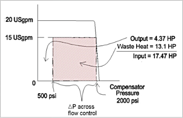
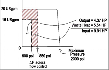
In this scenario, the system efficiency of the pressure compensated pump is approximately 25 percent while the fixed pump with load sensing achieves about 44 percent efficiency.
From the graphs 1 and 2 above, you can see that, in this condition, the pressure compensated pump circuit will be much less efficient due to the control’s inability to sense the load. In this high-flow/light-load situation, the fix pump with load sensing-type circuit is much more efficient.
This example points out that the nature of the control and the motion profile of the load, as well as duty cycle, must be clearly understood to choose the most efficient control option. It may be the most efficient to always specify a variable load-sensing pump for all circuits; however, if the duty cycle is intermittent usage, then a total cost case can be made for a fixed pump, load-sensing circuit.
In a previous article, I mentioned that closed loop hydraulic circuits represent an efficient circuit option. The advantage to these drives is that—because both the direction and speed of the load are controlled with the displacement of the pump—the throttling losses of open loop hydraulic circuits are eliminated. This type of circuit offers one of the most efficient hydraulic circuits possible.
In a typical closed loop circuit, there are two pumps: The main loop pump that controls the load and the charge pump that supplies make-up fluid for main loop leakage and also typically supplies pilot fluid for main pump control. The charge pump is usually fixed displacement and continually forces fluid across a relief valve that is typically set from 350 – 500 psi.
The charge pump size would typically be 10-15 percent of the main loop pump. So the continuous wasted energy is always at least the charge pump flow across the charge pump relief. The worst-case loss is when the main loop is at full load and the motor and pump are at maximum leakage. This could typically represent 10 percent of main loop total flow being forced through the pump and motor clearances at full load pressure.
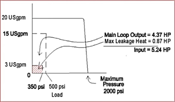
Using the same flow and load pressure numbers from the example above and assuming a charge pressure of 350 psi we see that, in the worst case, the closed loop circuit efficiency will be approximately 83 percent.
So, why aren’t closed loop circuits used everywhere if they offer such a distinct efficiency advantage? Considering that one main loop pump is required for each load, this is very practical on a stationary crane where there would be four main functions: Main boom, rotation, extension and winch. This makes for a very compact and efficient circuit.
However, as the number of loads grows and possibly the distant between them, having a separate closed loop circuit for each load becomes less practical from a machine design point of view. One input power source, capital cost wise, is very cost effective as opposed to having multiple closed loop circuits and the necessity of multiple prime movers. Of course, the long-term energy costs need to be weighed against this.
From an efficiency standpoint, there are clear standard options available. It’s a matter of understanding the combined flow-pressure profile of the loads and the machine duty cycle and then looking at capital and longer term costs to determine the best solution. Efficiency does have a cost, but we can calculate the real cost of proper design if we understand all the variables.
 Pat Jones, P.Eng, is the owner of Consolidated Fluid Power (CFD) Ltd., where he is an instructor and consultant with more than 20 years of hands-on experience in the fluid power industry.


