
There Is a Sieve In Your Roughness Gage
By George Schuetz
Quality Mahr metrologyIf the surface is not performing as specified, or is not what it's specified to be, an analysis of the surface needs to be conducted.
Many columns in these pages have talked about the importance of surface finish, and the equipment used to provide an indication that the end results of a machining operation are meeting target specs. We have talked about different methods of tracing a probe across a surface in order to gather data and analyze the surface, and we have learned that a surface generated on a part is the result of many controllable and uncontrollable inputs.
What we haven’t talked much about are the holes in surface finish gaging equipment.
But let’s go back and review how a typical surface may be generated on a lathe or turning center. As the part is turned in the spindle, a tool is dragged against the part, embedding the most basic roughness foundation. But the movement of that tool is the result of its motion relative to the machine ways. Out-of-straightness conditions will be passed onto the part. There are vibrations from the spindle, the coolant pump, and the press down the aisle, along with all the other environmental conditions that may be localized to the turning center. In the end, all these influences get superimposed on the part to make up the total profile of the part. As such, they influence how the surface will perform.
If the surface is not performing as specified, or the surface is not what it’s specified to be, an analysis of the surface needs to be conducted. To begin analyzing the surface the appropriate surface or waviness parameter must be selected, along with the correct setting for making the measurement.
Modern tracing methods have been standardized, using a standardized conical diamond moved across the surface in a controlled manner using a skidded or skidless drive. Traces are normally made 90 degrees to the lay, or predominant direction of the surface pattern.
Filters are a way to separate the different waveforms that are part of the surface’s total profile. Before starting though, it is necessary to understand the two basic features of a waveform: wavelength and amplitude. The total profile consists of multiple wavelengths and amplitudes superimposed on each other. When sampling a surface and collecting data, the surface data is filtered in several ways. For instance, the diamond radius, and the skid on a skidded instrument, filter the data by mechanical means.
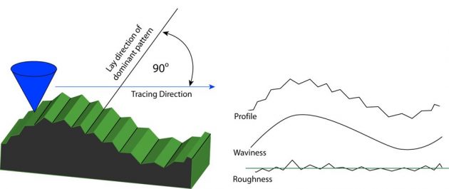
Other filters are used to separate wavelengths into roughness and waviness, for purposes of analysis. The short wavelengths are generally considered roughness, and the longer ones are waviness forms. The user must select the cutoff (or filter), which is the setting used to separate the profile into the component wavelength bands of roughness and waviness.
The cutoff value is the longest nominal wavelength to be included in roughness. Wavelengths longer than the roughness cutoff are included in waviness. These are the “holes” we were talking about above: the cutoff value functions like a sieve.
The sieve analogy is used to simplify the explanation of filters in surface metrology. A random mixed pile of sand, gravel and stones is put onto the sieve. The mesh of the sieve acts like a wavelength separator. The small sand particles that pass through the mesh are like roughness. The larger gravel will not pass through; this is like waviness. Stones larger than gravel are errors of form, which also do not pass through the mesh.
Cutoff setting is critical and cutoff lengths are set forth in national and international standards. When analyzing roughness, the cutoff selected must be short enough to exclude long wavelengths (waviness). These cutoff lengths are defined by ASME and ISO Standards. When reviewing the drawing of a part and surface specifications, the surface callout must specify the cutoff value for a surface finish specification in order for the drawing to be consistent with ASME.
Modern tracing methods have been standardized, using a standardized conical diamond moved across the surface in a controlled manner using a skidded or skidless drive. Traces are normally made 90 degrees to the lay, or predominant direction of the surface pattern.
Filters are a way to separate the different waveforms that are part of the surface’s total profile.
George J. Schuetz, Director Precision Gaging, has been employed with Mahr Federal Inc. for 40 years in the metrology business.  During that time, he has worked in the application’s areas for mechanical and digital indicators, mechanical gages, air tooling, electronic products, special gaging designs, surface finishing, and geometry gaging, and has worked with many companies to solve specific gaging problems. Presently, George is responsible for Precision Gage Product Management at Mahr Federal. Sign up to receive George’s Gaging Tips eNewsletters at www.mahr.com/gagingtips.
This blog originally appeared on www.mahrfederal.com. It has been republished on Design Engineering’s website with permission from Mahr Federal.