Getting into Gears
By Protomold
CAD/CAM/CAE Gears injection molding Protomold rapid manufacturingProtomold shows how to design gears for injection molding.
As design tools and techniques become more sophisticated and the arsenal of available resins grows, plastic continues to replace other materials in a variety of applications. Gears are among the mechanical parts being made increasingly of plastic. To effectively replace metal, the design and material must, of course, be suited to the demands of the application, but moldability of the part is equally important. All injection molding processes have specific capabilities and limitations, and if you plan to have Protomold produce gears it is crucial to understand the requirements of our molding process.
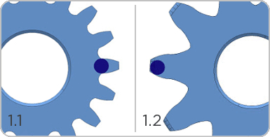
The primary challenge in the rapid injection molding of gears is the teeth. In order to be able to mold a gear we have to be able to fully fit an end mill into the area of the mold that will form a gear tooth. Figure 1.1 shows what happens when a gear tooth is too small for our smallest end mill. The mill cannot reach the end of the tapered tooth, so this gear cannot be produced using our process. Figure 1.2 shows a gear with teeth large enough to accommodate our end mill.

Figure 1: The dark blue dot represents the end mill that would be used to form a gear tooth in the mold.
Note that while the mill can reach the end of the tooth in Figure 1.2, it cannot reach into the corners of the squared off tooth. Teeth on this part will need to have more rounded corners. When you submit such a part for a ProtoQuote®, the inability to produce the squared outside corners will be noted in the design analysis, and you will have the opportunity to decide whether to modify your design accordingly. Depending on your design, this rounding could affect the engagement of gear teeth causing unacceptable “slop” in the operation of the gears. Your 3D CAD software can help you determine whether the modification will cause problems.
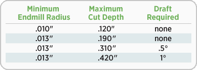
Another design consideration for gears is the side-to-side width of the gear. Wider gears may be needed to handle greater force, and the width of the gear determines the depth to which a mold will have to be milled. Deeper cuts require longer mills, and because long thin mills could wobble during cutting operations, our minimum mill radius increases with cut depth. If cut depth is great enough we use tapered mills to prevent wobble during cutting. As a result, very deep cuts require draft (see Figure 2).
When draft is required on gear teeth, it’s to allow for proper mold milling, not ease of ejection. While the amount of draft required for wider gears is small, as in the case with rounded gear teeth drafted gear teeth can affect the engagement of gears. In some cases, designing complementary draft into the teeth of mating gears can eliminate engagement problems.
Because they have to move and mate, most gears are made from a relatively small range of high-lubricity resins. For this reason, our ability to produce gears is not generally affected by resin choice. Following the above guidelines should allow you to design gears that can be effectively molded using our process. If moldability problems are found, they will be highlighted in your ProtoQuote design analysis.
www.protomold.com/DesignTips.aspx

