Modifying 3rd Party CAD data with Inventor Fusion 2012
By Imran Bhutta, ImaginIT Technologies
CAD/CAM/CAE Autodesk CAD Imaginit Technologies Inventor Inventor FusionFreely edit
In today’s Drafting world there are many different file types that users can import into Inventor 2012. This can range from IGES, STEP, CATIA, Solidworks, Pro/E, and Alias to name a few.
When these formats are imported into Inventor, most of the models are non-editable dummy solids. This can cause some issues in Inventor if you need to make a quick design change to the model. Inventor Fusion enables direct manipulation capabilities to allow users direct modeling for quick design changes without limitations.
In this exercise we will look at the best workflow to use Inventor and Inventor Fusion side by side.
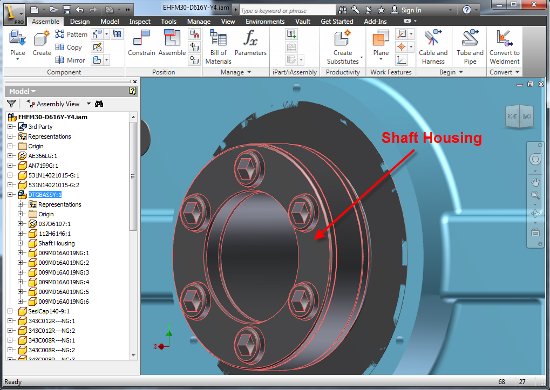
First open the 3rd Party CAD file in Inventor (in this example I will take a STEP file and bring it into Inventor).
When we imported the STEP File it created an assembly with subassemblies and parts as you can see in the model browser in the image above.
Now we want to make a design change to the number of hole instances on the Circular Pattern. Instead of 6 we would like the shaft housing to have 8.
Opening the Shaft Housing part we notice that it is a dummy solid and we cannot modify the Circular Pattern because there are no features available except for a Base Solid.
To manipulate the features we will use the Edit Form options Under the Model > Fusion Tab. Click on Edit Form and then you have to “Select a solid body or feature or Alias Freeform body to freeform edit”. (Simply click on a face or click on Base1 in the model browser)
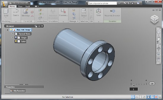
Once the Solid Body is selected Inventor will minimize and load the part in Inventor Fusion.
Inside Inventor Fusion you will notice that it still says Solid in the browser, but we can use the Find Features tool to extract and manipulate the base solid.
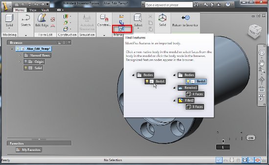
Under the Home > Manage you will see Find Features.
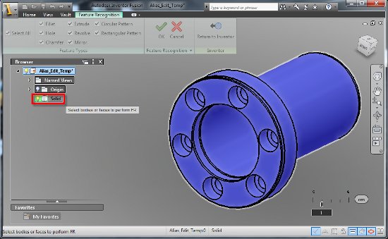
After you click on Find Features you will need to “Select Bodies or Faces to Perform FR” click on “Solid” under the Fusion Model Browser and then click OK.
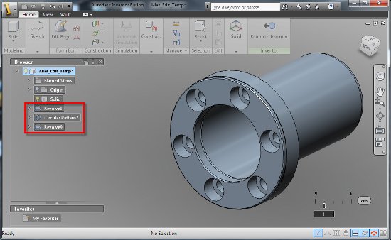
You should now notice some features under the Fusion Model Browser. In our example we see Revolve1, Circular Pattern2, and Revolve9. With the Circular Pattern feature created, we can now make the modification to our hole occurrences.
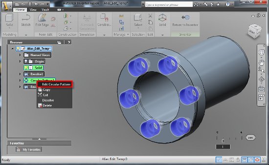
To edit the Circular Pattern, right click on Circular Pattern 2 and click on Edit Circular Pattern.
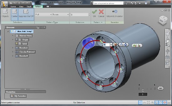
In the Text Box change the Occurrence from 6 to 8 and click on OK.
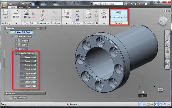
After you click OK you will see the new modified model with 8 Hole Occurrences instead of 6.
Finally click on Return to Inventor to take the model from Inventor Fusion back into Inventor.
In Inventor you will notice the part automatically updates with the new features we modified in Inventor Fusion.
As you can see, using Inventor Fusion was the best tool to make a quick modification on our design. Yes, you can go in and modify the dummy solid in Inventor, but that would have caused you to create a sketch on the face add material to the holes and then go in and create a hole circular pattern. And why use this method when we have the power of Inventor Fusion?
Imran Bhutta is a Manufacturing Solutions Consultant at IMAGINiT Technologies. He has 5+ years of experience working with Autodesk Inventor and supports all the Autodesk MSD and Data Management Software in the Solution Center.

