Non-graphic parts in Solid Edge assemblies
By Design Fusion
CAD/CAM/CAE CAD Design Fusion Solid EdgeHow to document components that don't require a model in Solid Edge.
Assemblies often contain components for which there is no model required, such as paint, grease, oil, labels, and so forth. These non-graphic parts still need to be documented in the parts list and bill of materials that are created for the assembly.
In Solid Edge, you can use the File Properties command on the Application menu in the Part and Sheet Metal environments to add custom properties to an empty part document. These custom properties allow you to define the required information for these types of parts. You can create two types of non-graphic parts: parts that require a unit type and quantity, and parts without a unit type and quantity.
Types of non-graphic parts
Parts with a unit type and quantity
Some non-graphic parts require a unit type and quantity. For example, you may require four liters of oil in an engine assembly. You can create a part document named OIL.PAR, and then set the unit type, Liters, in the part document. Later, when you place the oil.par document in the assembly, you can set the unit quantity using the Occurrence Properties command on the Edit menu.
Parts without a unit type or quantity
Other non-graphic parts require no unit type or quantity. For example, you may require a small quantity of grease between certain parts in the assembly. These types of part quantities are usually documented “As Required” on a parts list or bill of materials. For these types of parts, you define the custom properties and the text string you want in the part document. You do not have to edit the occurrence properties in the assembly.
Placing Non-Graphic Parts
Since non-graphic parts do not need to be positioned with assembly relationships, you can place the part in the assembly by holding the SHIFT key, and drag the part into the assembly.
Create a non-graphic part that uses units and value
This procedure shows you how to define custom properties for a non-graphic part that requires units, and a value for those units. Although no 3D model is required for these parts, they still need to be documented in a bill of materials or parts list. For example, you may require 4 liters of oil in an assembly.
Step 1: In the part document, choose Application menu→Properties→File Properties to open the Properties dialog box.
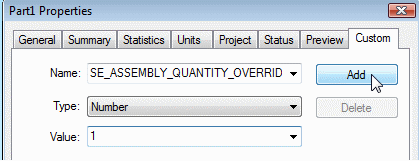
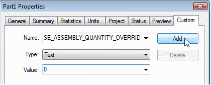
Step 2: On the Custom tab, in the Name box, type: SE_ASSEMBLY_QUANTITY_OVERRIDE.
Step 3: In the Type box, select Number from the list.
Step 4: In the Value box, type 0 (zero). Then click the Add button.
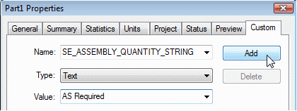
Step 5: In the Name box, type: SE_ASSEMBLY_QUANTITY_STRING.
Step 6: In the Type box, select Text from the list.
Step 7: In the Value box, type the unit and number of decimal places you want. For example, Liters;4. Then click the Add button.

Note: You must separate the unit type and decimal places with a semi-colon (;). If the number of decimal places you want is 2, you do not need to enter a value for the decimal places.
To use the custom properties in an assembly, do the following:
Step 1: Place the part in the assembly.
Step 2: Select the part in the PathFinder tab or the graphics window, then on the shortcut menu, choose Occurrence Properties.
Step 3: On the Occurrence Properties dialog box, type the quantity value in the Quantity cell for the occurrence. Notice that the unit value you specified in the part document is displayed in the User-Defined Quantity column.
Tip:
- You can place a non-graphic part in an assembly without applying relationships by holding the SHIFT key, then dragging the part into the assembly.
- You can also set the quantity value using the Occurrence Properties button on the Place Part command bar.
- If you use many non-graphic parts at your company, you can create a template that has the non-graphic part custom properties defined.
Create a non-graphic part that is unit less
This procedure shows you how to define custom properties for a non-graphic part that does not require units. Although no 3D model is required for these parts, they still need to be documented in a bill of material or parts list. For example, you may require a small quantity of grease that on the parts list is documented “As Required”.
Step 1: In the part document, choose Application menu→Properties→File Properties to open the Properties dialog box.
Step 2: On the Custom tab, in the Name box, type: SE_ASSEMBLY_QUANTITY_OVERRIDE.
Step 3: In the Type box, select Number from the list.
Step 4: In the Value box, type 1 (one). Then click the Add button.

Step 5: In the Name box, type: SE_ASSEMBLY_QUANTITY_STRING.
Step 6: In the Type box, select Text from the list.
Step 7: In the Value box, type the constant text you want. For example: As Required. Then click the Add button.

To use the custom properties in an assembly, do the following:
- Place the part into the assembly. The “As Required” property is automatically recognized in the Occurrence Properties dialog box. To review the part’s properties, select the part in the PathFinder tab or the graphics window, then on the shortcut menu, choose Occurrence Properties.
Tip:
- You can place a non-graphic part in an assembly without applying relationships by holding the Shift key, then dragging the part into the assembly.
- If you use many non-graphic parts at your company, you can create a template that has the non-graphic part custom properties defined.
- You can also set the part properties with the Occurrence Properties command on the shortcut menu when a part or subassembly is selected.
- When you select the top level assembly entry in PathFinder, then click the Occurrence Properties command, the entire assembly structure is displayed in a bill of materials format. You can use the (+) and (-) symbols to expand and collapse the assembly structure.
- When you select one or more parts or subassemblies, the selected occurrences are displayed in a table format that cannot be expanded or collapsed.
- If you need to change the properties of a subassembly, you must first check out all subassemblies where the occurrence properties are being modified. Then the documents can be saved and checked back in to Teamcenter.
Set part properties in an assembly
1. Click a part or subassembly in the assembly.
2. Right-click, then choose Occurrence Properties on the shortcut menu.
3. In the Occurrence Properties dialog box, set the options you want to use.
Tip:
-
*Text passages taken from Solid Edge Help files.

