
Setting up a Parametric Dimension Study in Inventor Simulation
By Nino Caldarola,B.Sc. CET, IMAGINiT Technologies
CAD/CAM/CAE FEA analysis Imaginit Technologies Nino CaldarolaTake static analysis to the next level by analyzing multiple design variants with a single setup.
 The Simulation functionality within Inventor incorporates a useful and unique toolset called “Parametric Dimension” Study. This takes the normal Static Analysis to a higher level by allowing multiple variants of a design, either a Part model or an Assembly, to be tested within the same setup. This eliminates the requirement to have multiple analysis files for the same geometry, which can be changing parametrically and thus can also be studied efficiently with the environment.
Let’s take a look at a possible scenario:
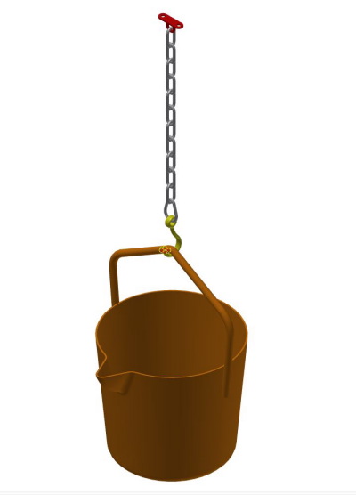
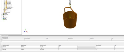
We have a ladle bucket, which is suspended from a ceiling hanger, and we are required to see what the stresses are on several chain sizes and lengths. The chain is the same material, however comes in different link lengths and link diameters. The scope may be, which sizes would be adequate for a specific weight (Applied Force and Gravity) that the bucket needs to contain as it’s suspended.
Our first step is to set up a simple analysis to test a default sizing of the model.
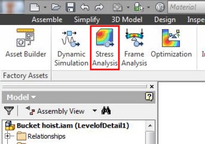
We initiate the Stress Analysis Environment.

We will start by doing a Single Point analysis. The process is the normal setup procedure within Inventor’s Simulation Environment to performance an Assembly Analysis.
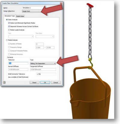
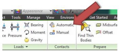
Since this Assembly requires “Point and Line”, contacts — due to the chain links contacting each other — Bonded is inappropriate.
By changing the Type to Sliding/No Separation, the links will react in the correct manner in the Analysis. The Tolerance is also adjusted (0.5 in) to ensure that all relevant surfaces are evaluated and the contacts established.
After the Contacts have been applied, the remaining portions of the normal setup can be applied.
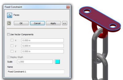
The Hanger is the suspension component and receives a Fixed Constraint to simulate it fastened to the ceiling.
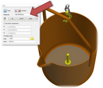
The Bucket’s bottom has the required Force applied to it to simulate the weight of the material (Liquid or Solid) that it will contain. In our experiment, we apply a value of 200 Lbf (Pounds Force) to simulate the weight.
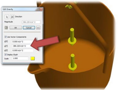
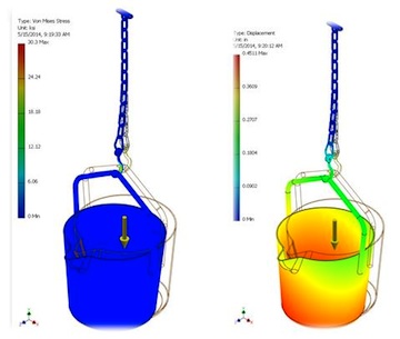
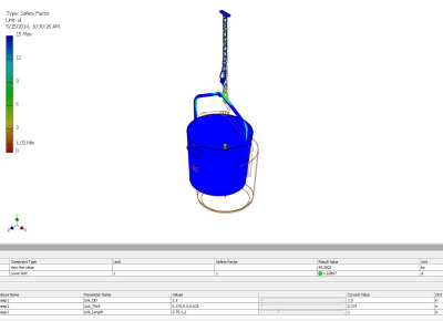
We also add the Gravity component to our load in the correct vector direction. Finally, we Mesh the model and run the Simulation.
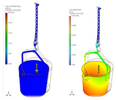
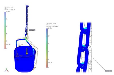
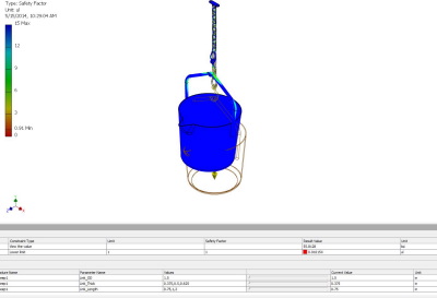
Examining the results, we now can take the next step and preform a variant study using the “Parametric Dimension” option.
It should be noted that a Single Point is not necessary but provides a good yard stick to get a sense of what kind of results can be obtained.
Preparations for Parametric Dimension Study
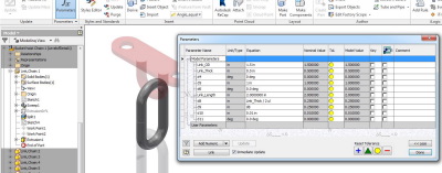
It is good practice that before the study is started to go back into the modeling environment to rename the parameters that are intended to be used in the study. Renaming allows the user to easily select the correct variable that will be used in the Analysis.
Since our concern is primarily the links, we rename the link parameter accordingly.
After renaming, the Analysis Environment is activated and we can use the original set or create a copy of it. The copy in this case simply changes the Analysis so that we will be able to use the Parameter Table in the Analysis.


Before activating, we need to select our renamed variables; this is done by expanding the Assembly node in the Browser and selecting a link. RMB over one of the links. Then select “Show Parameters”.
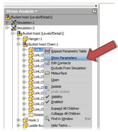
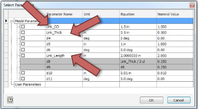
Check the Parameter(s) that are intended to be used and click ok.
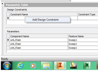
The Parametric table is then launched. This shows the selected parameters and is now ready to be configured.
Design Constraints are then added. The Constraints that are used are Von Mises and Safety Factor results. These are place by RMB on the empty “Design Constraints” field and then selecting from the list in the dialog box.
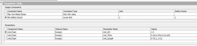
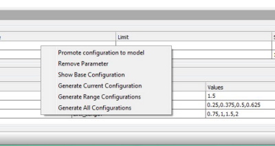
The table allows us to create multiple values on the fly for the Parameters and also sets the results criteria in the Constraints.
After these have been set, generating all configurations before running the Analysis is a best practice.
With the various configurations already existing, the Simulation runs more efficiently since it does not need to create the variant before it can be analysed.
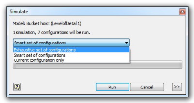
Finally the Simulation can be run using Exhaustive to capture every variation.
In conclusion, the use of the Parametric Dimension Study is a good way to compare the results of multiple choices and helps the decision maker select the best combinations.
Since many different Parameters can be used to set up the scenarios, this functionality within Inventor provides an addition facet to the Simulation features within Inventor. Parametric Dimension Study gives Inventor a unique method to extend it validation functionality.
Check out more Autodesk tips and tricks on IMAGINiT Technologies’ Manufacturing Solutions Blog.
http://blogs.rand.com/manufacturing/
Nino Caldarola is an Applications Specialist with IMAGINiT Technologies. As a result of working in the automotive, agricultural equipment, and aerospace industries before teaching CAD for the past fourteen years, Nino is extremely knowledgeable and comfortable in the latest CAD technology and enjoys presenting in a classroom environment. The Winnipeg-native is also well known for his life-sized motorcycle and turbo prop engine designs that were 3D printed and displayed at Autodesk University.