Wrapping or projecting a sketch in Solid Edge
By John Pearson, Senior Technical Trainer and Application Specialist, Designfusion
CAD/CAM/CAE 3D Dojo CAD Design Fusion John Pearson Solid Edge tutorialPlacing text, or any sketched pattern, on non-planar surfaces in SE is as straight-forward as a couple of mouse clicks.
Last month’s blog entry (Placing and using text as geometry in Solid Edge) prompted several calls asking if the sketched text could be placed on non-planar surfaces.
The answer is yes. There are two methods to achieve this:
1) Wrap Sketch command
2) Project Curve command
Wrap Sketch Command
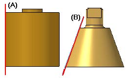
The Wrap Sketch command can be used to wrap a sketch around any analytic surface, such as a cylinder or cone. Before using the command, you must create a sketch on a plane that is tangent to the surface. For example, proper reference plane tangency to a cylinder (A) or cone (B) is as shown.
Once the sketch is created, you can select the Surfacing tab –> Curves group –> Wrap Sketch command.
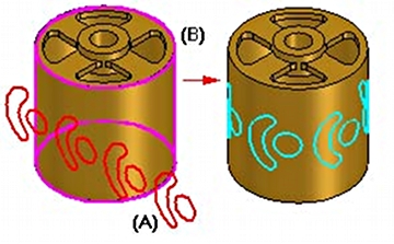
Next you select the analytic surface (A) that you want to wrap the sketch around.
Then select one or more sketch elements (B) that you want to wrap.
After you wrap a sketch onto a surface, you can use the Normal Protrusion or Normal Cutout commands to construct a protrusion or cutout feature using the wrapped elements.
Tips:
- When selecting more than one surface, the set of surfaces must be connected.
- The sketch plane must be tangent to one of the input surfaces.
- You can select individual sketch elements, a chain of sketch elements, or the entire sketch using the Select options on the command bar.
Project Curve Command
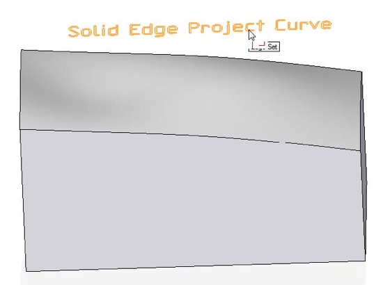
The Project Curve command projects 2D or 3D curves onto any surface or set of surfaces.
First you must have a sketch or curve created. You then select the Surfacing tab –> Surfaces group –> Project Curve command.
You can set the options to project along a vector or to project normal to the selected surface.
For the ‘Along vector’ options, do the following steps:
Click the curve or point you want to project onto a surface and then click the Accept (check mark) button.
Click the surface onto which you want to project the curve and then click the Accept (check mark) button.
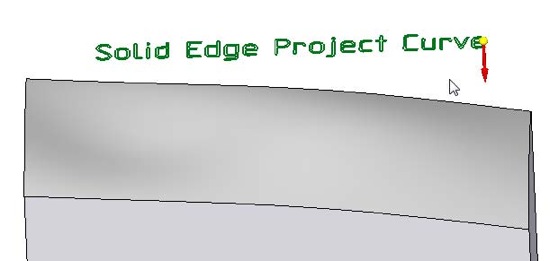
Click to specify the direction you want to project the curve.
Finish the feature.
Tips:
- When you are projecting a planar curve along a vector, the Projection Plane Step is skipped, and the plane the curve is on is used to define the normal direction in which to project the curve. If you want to project along a different normal, you can click the Projection Plane Step button and define the plane you want.
- You can also use the Project Curve command to project a point onto a surface.
- You can use the command bar to specify that you want to project a single element, a chain of elements, a point or an entire sketch.
For the ‘Normal to selected surface’ options, do the following steps:
Click the curve or point you want to project onto a surface and then click the Accept (check mark) button.
Click the surface onto which you want to project the curve and then click the Accept (check mark) button.
Finish the feature.
Tips:
- You can also use the Project Curve command to project a point onto a surface.
- You can use the command bar to specify that you want to project a single element, a chain of elements, a point or an entire sketch.
After you wrap a sketch onto a surface, you can use the Normal Protrusion or Normal Cutout commands to construct a protrusion or cutout feature using the wrapped elements.
 John Pearson is a Senior Technical Trainer and Application Specialist at Designfusion. He has over 24 years’ experience in the CAD/CAM industry, is a Certified Adult Trainer and has taught evening CAD courses at colleges in Ontario. He is also a major contributor of articles on the Design Fusion blog.


