
3 things you didn’t know you could do in Solid Edge
By By John Pearson, DesignFusion
CAD/CAM/CAE CAD Designfusion John Pearson Solid EdgeSmart select, intuitive model rotation and unconventional dimension tricks help save design time in Solid Edge.
As a support team member, and technical trainer, part of my job is to learn the technology inside Solid Edge. Therefore, I’m allotted time to learn, test and research the latest technology. But as I’m sure many of you will agree, this is a privilege most users don’t have. Users are under the gun to meet deadlines and therefore often stick to what they know, even if it’s not the most efficient approach. As a result many users are unaware of the full potential of Solid Edge.
On more than one occasion I have received requests for custom programming for capabilities that already exist in Solid Edge. I often find myself saying “Did you know that you can do this in Solid Edge already”. With this in mind I thought it might be a good idea to start recording some of these moments and share them in our blog. So below are some of the questions I get from our customers along with how to do it in Solid Edge.
I have to delete a part list from my draft file, is there a quick way to delete all my balloons, or do I have to pick them individually?
Did you know that you can do this in Solid Edge using the SmartSelect command?
To select all the balloons at once do the following steps.
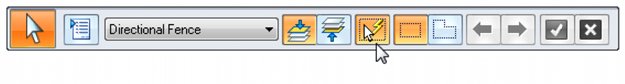
- Pick the Select tool to launch the Select tool command bar.

![]()
- Select the SmartSelect icon from the Select tool command bar.
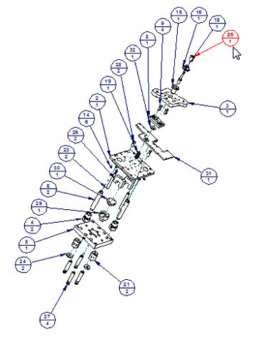
- Select one of the balloons from your view.
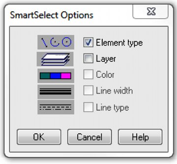
- The SmartSelect Options dialog box appears. Check Element type and click OK.
- Notice that all the balloons highlight.
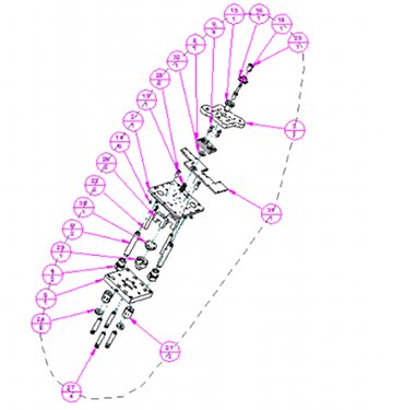
- Hit the Delete key and they are all deleted.
The SmartSelect command searches the active sheet for other elements with similar attributes, such as element type, color or line width. All matching elements are automatically added to the selection set. Now you can make changes to the selected elements all at once. This is ideal to make changes or delete dimensions, lines, callouts, etc. in the Draft environment.
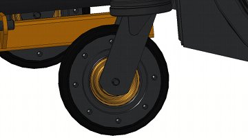
I have a large assembly and when I’m zoomed in and try to rotate the part, it flies off the screen. Is there a better way to control the rotation?
Did you know that you can do this in Solid Edge using the middle mouse button? The problem here is that the default center of rotation is (0,0,0). So if you are zoomed in, away from the origin, any rotation appears to rotate out of view. What you need to do is change the center of rotation by following these steps:
- Zoom into the area you want to view.
- Click your Select tool. Notice that the cursor has a small gold box beside it.
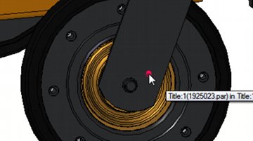
- Click the middle mouse button, in an empty space, and the gold box will disappear.
- When the gold box disappears, move the cursor over the model. Notice the bright pink dot attached to the cursor.
- This bright pink dot represents the center of your next rotation. Move it to where you want the center of rotation to be, and then hold down your middle mouse button to rotate.
- Notice the rotation symbol on the cursor, and that you are rotating around the pink dot.


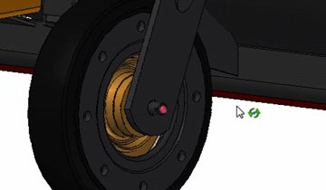
When you release the middle mouse button you are placed back into selection mode. You can also use this in the part or sheet metal environments. For more information, and additional mouse tips, read the Solid Edge Help docs under the “Using the mouse” heading.
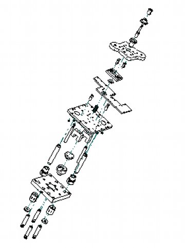
I want to place a dimension between two points that are not horizontally or vertically aligned.
Did you know that you can do this in Solid Edge using the Distance Between command? All you have to do is follow these few steps:
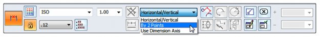
- Select the Distance Between command.
- On the command bar, change the Horizontal/Vertical option to By 2 Points
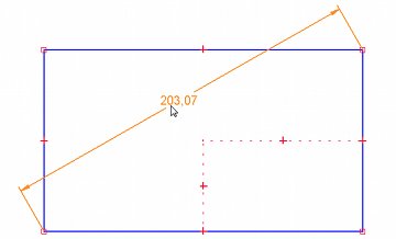
- Select the 2 keypoints and place the dimension.
![]()
For more information, and additional options, read the Solid Edge Help docs under the “Dimensioning overview” heading.
These are actual questions that I have received many times from our user base. It just goes to illustrate that Solid Edge is not always being used to its full potential and that there is always room for improvement. The more you understand about the software, the more efficient you will become.
Design Fusion
 John Pearson is a Senior Technical Trainer and Application Specialist at Designfusion. He has over 24 years’ experience in the CAD/CAM industry, is a Certified Adult Trainer and has taught evening CAD courses at colleges in Ontario. He is also a major contributor of articles on the Design Fusion blog.