Automating Inventor part creation with Excel, Part 2
By by Nino Caldarola, Application Engineer, Manufacturing Solutions, ImaginIT Technologies
CAD/CAM/CAE Autodesk CAD InventorHow to use Excel to create multiple part (or assembly) variations in AutoCAD Inventor.
Part feature are controlled by the use of parameters and these are based on good sketching practices as well as a good understanding of how each interacts with each other. The manipulation of these vital control elements can be achieved in many ways.
In Part 1 of this tutorial, we saw how manipulation from an external source (MS Excel, in particular) can simplify the creation of multiple variations of parts and assemblies.
However, parts — or more specifically their parameters — can communicate with each other by exporting them out in the Parameters manager, then linking them to one or more parts to form a parent/child hierarchy. In Part 2 of this tutorial, we’ll be looking at an example of this.
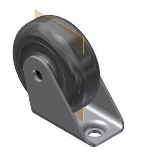
We’re using two parts in this assembly — the Wheel and the Bracket — to create the Caster assembly. We are going to allow the bracket to size the wheel by feeding the bracket’s parameters to the wheel and thereby drive its width and diameter.
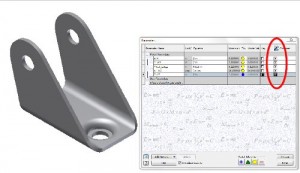
We’ve renamed and filtered the various parameters that we will be using to change the size of the bracket. We’ve also checked the export column to allow access of our primary parameters by other parts.
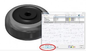
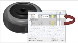
We’ve also renamed the various parameters in the wheel to allow easier access to the parameters that we need to link to create the part-to-part relationship. We’ll now link to the parent part (the bracket) to access the parameters.
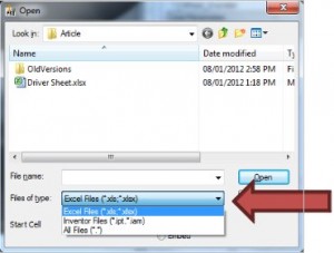
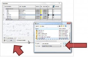
In the first step, we browse for the parent part that we’re linking to by changing the “File of Type” to reflect the IPT/IAM rather than a spreadsheet.
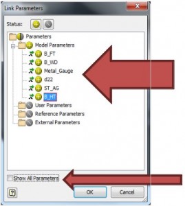
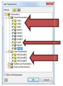
Select the parameters in the dialog box. These will then be inserted into the child part as a user linked below the modeling parameters. (Tip: Uncheck the “Show All Parameters” to limit your choices to only the exported one.)
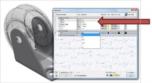
The last thing we need to do is link up the User’s parameters to the Model parameters in order to drive that part(s) as a child of the parent. Therefore, the wheel is the child of the Caster bracket.
In this view, a multi-value numeric Users’ parameter was created to allow only certain sizes of the bracket widths.
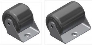
Here are some of the results.
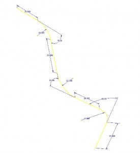
Let’s take a look at a more complex example. Here is the sketch of a pipe. All the require parameters are shown and the sketch is actually two 2D sketches combined into a 3D sketch.
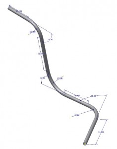
Here is the pipe that has been swept. The issue is we can get the flat length of the pipe by doing a loop measurement; however, we’d like to have a representation of it as a straight piece of pipe before bending. Here’s a way of getting that piece of information using parameter linking.
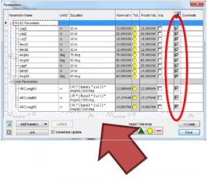
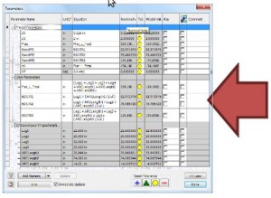
This is a view of the Parameters Manager for the pipe. I’ve created three user parameters: ARCLength1, ARCLength2, and ARCLength3. These will calculate the arc lengths for the bends and are then exported to be recovered in a “representation” part as a child of this pipe part. The purpose of this new part is to create a flat representation of the pipe itself. The value calculated can also be used as a custom property in the title block of the drawing of the pipe.
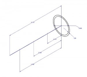
Here’s is the “representation” part sketch before the linking occurs.
Go through the exact same process as above mentioned to link the two parts together to allow access to the parent parameters.
We’re only “harvesting” a few parameters this time. This is because we don’t need the bends or the angles since we’ve got the arc length user parameters. I’ve selected only those that are going to be used to calculate the flat length. This will also eliminate bringing over unnecessary parameter to the new part.
I’ve created a Flat Length user parameter and some optional parameters to indicate the position of the “Start of Bend”. These are then linked up to the new “Representation” part and new as we change the value in the finished pipe, it will automatically give use the Flat version with total pipe length required and also the locaton of the “Center of Bend” given.
Here’s the part generated by the parent/child linking. The total length is exactly the length of the neutral axis of the formed pipe. This method uses the tools available in Inventor from day one of the application. With the introduction of ilogic, this process can also be incorporated as a rule to eliminate some steps; however, the principles are the same.
 Nino Caldarola is an Application Engineer, Manufacturing Solutions for ImaginIT Technologies Canada. As a result of teaching CAD for the past fourteen years, Nino is extremely knowledgeable and comfortable in the latest technology and enjoys presenting to audiences in a classroom environment. He has also worked with customers in concept development and prototyping in the mechanical and manufacturing engineering fields. His personal development projects have taken him into the new technologies of rapid prototyping and 3D Print and his ultimate achievements include two models (recognized as the most complex and largest in the world) that have been 3D Print produced and exhibited at Autodesk University 2009 and 2010. Both models are on display at the Autodesk Gallery.

