
Common Mistakes made by novice users – Part 2 of 3
By Manny Marquez, Design Fusion
CAD/CAM/CAE Design Fusion Manny Marquez Solid EdgeHow best to leverage direct modeling tools in Solid Edge’s reference planes, sketching methods and base features.
 When talking to customers and looking over their models for unrelated issues, I occasionally recognize simple mistakes that normally consist on how the part was initially created. Typically, I will explain to them why the part should be modeled in a specific way, following best practices.
The way a part is modeled plays a big role on the downstream process, usually when trying to modify the model in Solid Edge’s “ordered” or parametric environment.
Here are the focus areas for the second part of this post: (See part one on Solid Edge’s direct editing and ordered modeling modes)
• Reference Planes
• Sketching
• Base feature
• Treatment Features
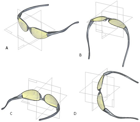
Correct plane selection
1. A reference plane is a flat surface that is typically used for drawing 2D profiles in 3D space; this will be your foundation for your model.
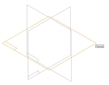
2. It is always a good practice to have the part center to all base plane on X,Y,Z. in this instance (B) would be the correct method.
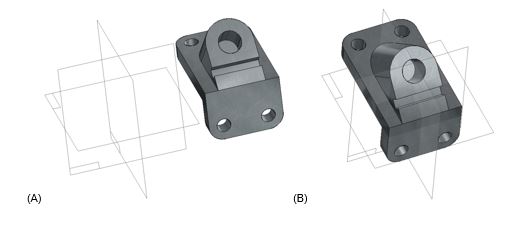
Choose the correct reference plane
3. The following example illustrates the results of using different reference planes to draw the first profile. For this sample,
using the “xy top” plane (A) the result is a part which is easiest to visualize in the isometric view (ctrl + I).
4. You can also think of consumer products, how you can better visualize the product, again the example (A) is the best to comprehend it in your mind.
Correct sketching method
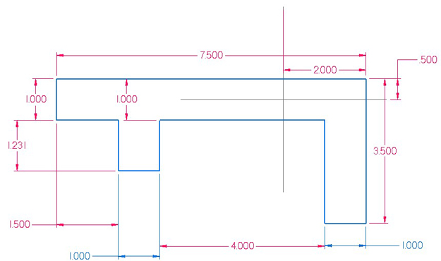
5. Sketching to a correct scale.
Below is a shape of a profile, I have placed a green dotted (reference) line on (X) 7.5 and(Y) 3.5 to indicate overall length and to visualize the scale. When you start placing dimensions, that’s when you realized how small or big your sketch is.
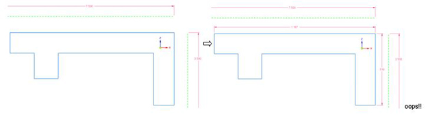
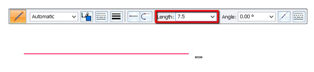
6. It is always a good practice to draw a line to actual length or approximate of the base profile. So as you start to sketch your profile, it will not deviate when you are entering true values.
Below is the same sketch out of scale, placed dimensions, enter true values. See how your sketch starts to look more like a maze. Not a good practice!
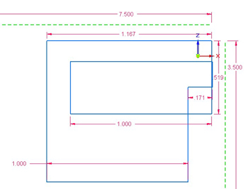
Below is a sketch scaled properly with correct dimensions.
Base features
7. Consider these questions when starting a new model:
What is the best profile for the first feature on the part? Which reference plane should it be drawn on? Are there symmetric features on the part? When constructing a 3D model, it is helpful to evaluate the basic shape of the part, and develop a plan as to how you want to construct the model. The first feature created for a part or sheet metal model is called the base feature.
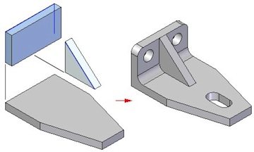
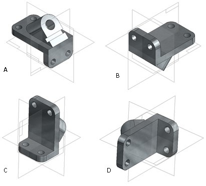
Choose the best profile for the base feature.
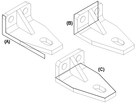
8. Profile C would be the best choice. It defines the basic length and width of the model and includes the tapered end. Two additional protrusion features complete the basic shape of the part. A hole feature, a cutout feature, and a round feature complete the part.

Treatment Features
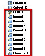 9. A treatment feature is a feature applied to faces and edges of a solid body. The most commonly used treatment features include rounding an edge(s), chamfering an edge(s), adding draft and thin walling a part. For best results, add treatment features to your model as late as possible in the design process.
www.designfusion.ca
For more Solid Edge tips and tricks, check out Designfusion’s blog.
www.designfusion.com