Creating Bend and Punch Tables in SolidWorks
By Jeff Brown, Hawk Ridge Systems
CAD/CAM/CAE CAD Hawk Ridge Systems sheet metal SolidWorksTake the clutter out of complex part sheet metal drawings in Solidworks.
Bend tables and punch tables enhance the clarity of your drawings by moving annotations from your drawing views into a table. While these tables are not always necessary, complex parts with many bends or formed features in a small area may suffer from information overload in the drawing view. One way to lessen the clutter and effectively communicate your design is to move the bulk of that information into a table. This segment will explore just that.
First, let’s take a look at bend tables.
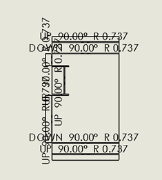
Consider the drawing view in the following picture. With this many bends, the view can become cluttered. Although we can reduce the font size, there are limited options to organize this drawing view:
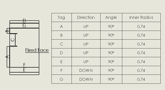
Now, let’s take a look at the view when the bend table is used.
The bend table assigns labels (letters or numbers) that correspond to a specific bend in the table. This moves the majority of text off of the view and into a table, making the view easier to understand.
Now, let’s look at punch tables.
As with the bend notations, a complex part can cause the drawing view to become cluttered. Here I have a small part with many punches (louvers, lances, and embosses). In the first view I have dimensioned each punch so that it can be located.
It is reasonably clean with ordinate dimensioning; however, using a punch table will take our drawing to the next level. The following view uses a punch table. Like the bend table, a number or letter is used to represent each punch, and the location, orientation, punch id, as well as other information can be listed in the table. Notice that the locating information is based on a datum that the user defines, either by selecting a vertex or by selecting two axes.
So where do we find these amazing tools? While in a SolidWorks drawing document, they can be found under Insert > Tables. This is the same area where you would insert a Bill of Materials table or Weldment Cut List. Now you can showcase your designs in a clean and clear drawing that minimizes text on the drawing view, and maximizes information on the drawing sheet.
Certified SolidWorks Expert, Jeff Brown, teaches numerous classes in the Southern California area, and has presented at the annual SolidWorks Launch events. Jeff holds a degree from USC in Aerospace Engineering and is an expert in SolidWorks Composer and SolidWorks Electrical, and is an Advanced Sheet Metal and Advanced Weldments Specialist.


