Creating insert notches in sheet metal with Solid Edge
By John Pearson, Senior Technical Trainer and Application Specialist, Designfusion
CAD/CAM/CAE CAD Design Fusion John Pearson sheet metal Solid EdgeSolid Edge's
Recently I was asked if Solid Edge had a special command for making insert notches in sheet metal. These notches are used to insert tabs or pins in various assemblies. The image above shows a few examples of the type of notches I refer too.
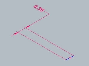
To create these notches and others like them, I always use the Bead command in the Solid Edge sheet metal environment. Although designed to create beads, it also creates open ended beads, which are notches. To do this you start with a sketch which represents the length of the bead. For example, I may need a 6.35mm (1/4 “) wide notch, so I create a 6.35mm sketch line.
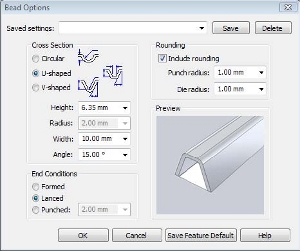
Using the bead command options, I select the overall shape of the notch. For example, I may need a U-shaped notch 6.35mm high and 10mm wide.
Notice that I set a lanced end condition. I could also use a punched end condition which allows me to extend the cutout portion of the notch.
If this is a feature that I will use often, I can save the settings for easy recall in the future.
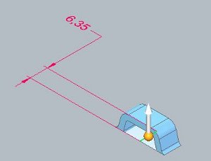
Once I say OK to the options dialog, I simply select the direction that I wish to apply the notch.
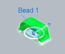
The resulting bead feature can be edited by adjusting the options or editing the sketch. It can also be added to a feature library.
So my answer to the original question: “Does Solid Edge have a special command for making notches in sheet metal?” is yes. It’s called the Bead Command.
 John Pearson is a Senior Technical Trainer and Application Specialist at Designfusion. He has over 24 years’ experience in the CAD/CAM industry, is a Certified Adult Trainer and has taught evening CAD courses at colleges in Ontario. He is also a major contributor of articles on the Design Fusion blog.


