
A lack of support
Staff
Power Transmission igusHow to design unsupported vs. gliding cable carrier applications.
The cable carrier is an integral part of any machine design and should be considered early on in the design process. It can be implemented in a variety of ways, depending on the motion of the machine, but the most common is a horizontal, unsupported, short-travel installation. In this type of application, the upper run of the carrier operates without touching the lower run throughout the entire length of travel.
 If the length of travel is too long for an unsupported installation, it is considered a gliding, long-travel application in which the cable carrier glides on itself. A guide trough and glide bar must be used to support the carrier.
This quick guide shows how to implement cable carriers and critical rules to follow during the design and installation process.
Designing Unsupported Applications
If the upper run of an Energy Chain cable carrier operates without touching the lower run over the entire travel, it is classified as an unsupported application.
 The maximum service life of a cable carrier in an unsupported application is dependent on the type of cable carrier selected, as well as the fill-weight of the carrier. The fill-weight creates three sub-sets of unsupported cable carrier applications:
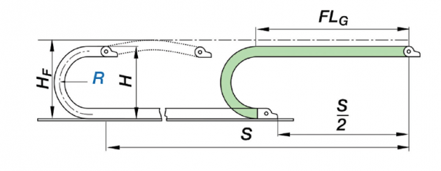
- Unsupported / “straight” run (FLG): This type of application is always preferred, as the cable carrier is able to run quietly and smoothly, without any exposure to additional vibration due to sag in the upper run of the carrier. In an FLG application, the upper run either has camber (curve along the upper run), is straight, or has a small amount of sag, between 0.39 and 1.97 in., or 10-50 mm, depending on the size of the cable carrier.
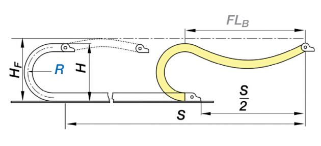
- Unsupported / permitted sag (FLB): An FLB cable carrier installation has sag in the unsupported run that amounts to more than .39-1.97 inches, but less than the carrier’s maximum sag allowance, which is dependent on the type of carrier being used. FLB applications are permissible in most cases, but can become problematic if the travel frequency or acceleration of the cable carrier is high.
- “Critical Sag”: If the cable carrier’s upper run has sag greater than permissible for an FLB application, it is referred to as having “critical sag.” These types of installations must be avoided or reserved for extreme circumstances. While a cable carrier should never be installed with critical sag, some applications may reach the stage of critical sag after a long period of use. The cable carrier should be replaced at that time.
Designing Gliding Applications
For long travels, the upper run of a cable carrier rests on the lower run, gliding partially on the lower run of the carrier, and partially at the same height on a glide bar. For lateral guidance in a gliding application, a guide trough is required.
 Guide troughs allow for cable carriers to operate smoothly and securely in long-travel applications. The height of a guide trough must be at least twice the height of the carrier links, and the sides must provide a chamfered opening, with slightly wider inner width than the outer width of the carrier.
When the upper run cannot glide along the lower run, glide bars must be installed along the sides of the trough.
Important notes for installation of troughs and glide bars:
- Properly align all parts upon installation
- All screw heads should be flush with the trough
- Ensure a smooth, level transition between the end of the chain and the glide bars
- Ensure a solid connection with the glide surface
Differences in Speed, Acceleration and Service Life
For unsupported and gliding applications, the acceleration of the cable carrier is a critical parameter to consider. High accelerations can cause the carrier to vibrate, reducing the service life. In an unsupported application, where sag is greater than the FLG (unsupported, straight) value mentioned above, this can become particularly dangerous.
Maximum levels of acceleration and speed in an unsupported application can only be achieved with carriers in an FLG design. Energy Chain cable carriers used in this type of design can sustain very high loads, speeds and accelerations in unsupported applications. In the igus test lab, peak accelerations of 2,572 ft2 (784 m2) have been achieved during continuous use in specialized applications.
This article was provided by igus.