
DIN or AGD: What’s Right For Me?
Staff
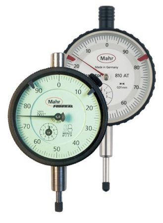
Quality gaging Mahr FederalIt's becoming more and more common to see gages made to different standards as they come from different countries.
A longtime friend of mine from Russia once told me that eventually the US would be metric and that we would get there “one inch at a time.” While we are not a metric country yet, the manufacturing industry tries to be international and that often means producing parts in metric units. Certainly most of the automotive industry has moved on. As parts and manufacturing processes are moved around the world, it’s becoming more and more common to see gages made to different standards as they come from different countries; for example, DIN standards (from Germany/Europe) or JIS standards from Japan.
In the US, most gaging specifications were long ago gathered and documented to AGD Standards (American Gage Design), but through the years these have been published under ANSI/ASME (American National Standards Institute/American Society of Mechanical Engineers).
For most of Europe, gages are designed and built to DIN standards (German Institute for Standardization and the German ISO member). This standard covers more than just German products, as it is a member of the European Committee for Standardization (CEN) covering 30 EU members that utilize DIN specifications.
So what’s the big deal whether a gage—let’s say a caliper—is an ASME design or a DIN compliant design? To the user, usually not much. There may be a difference in how or if performance specs are defined or the product is calibrated. On the other hand, however, there are products that are physically different between the AGD and DIN standards in both design and philosophy of use. A few that come to mind include dial indicators, master rings, and discs that differ in both their physical shape and how they measure.
Whether you are receiving a new gaging solution from another country or looking through the catalogs of gage suppliers with world presence, it does not hurt to have a basic knowledge of what the differences are in some of these world products. We will start with Dial Indicators and over the next few months take a look at some other products.
 All dial indicators are basically mechanical amplifiers. Through gearing, they take a linear motion and amplify it to a rotating hand that allows you to “see” what the displacement is. How this mechanical amplifier is packaged and tested is what the specifications are all about.
General Use & Philosophy
US (ASME) dial indicators are primarily used for comparative purposes in a bench gage or stand to compare a part’s measured value to a master. Thus, they more commonly have a balanced dial with a “+” to the right to indicate a larger size. Dial indicators are available in various configurations and with longer ranges for various measuring applications. Dial indicators are also commonly furnished with a lug back or alternate back for fixture mounting.
The use of DIN indicators is slightly different as in most cases the operator is using them to determine if parts are within allowable tolerances. These style indicators are typically furnished with continuous faces, rev-counters and have longer measuring ranges.
Sizes
There are numerous outside diameter sizes of indicators that may be determined by use (portable or bench mounted) and how far from the reading the customer is.
AGD/ANSI specification calls out five standard sizes:
• AGD & ANSI Group 0: 1.25″ diam. (32 mm)
• AGD & ANSI Group 1: 1.75″ diam. (44 mm)
• AGD & ANSI Group 2: 2.25″ diam. (57 mm)
• AGD & ANSI Group 3: 2.75″ diam. (70 mm)
• AGD & ANSI Group 4: 3.625″ diam. (92 mm)
DIN is not as concerned about specific sizes but rather specifies that the indicator must fall within a certain size range, e.g. 55 mm – 60 mm. It’s left up to the manufacturer to determine the size of the indicators provided. Most suppliers will thus provide an indicator with a 58 mm diameter but also offer other sizes such as 34 mm, 50 mm or 108 mm.
Because the Group 2 AGD & ANSI indicator is fairly close to the DIN 58 mm, they are interchangeable in most protective housings designed for either indicator.
Stem Diameters and Accessories
This is where the details come into play. AGD/ANSI inch indicators use a .375″ stem mounting and a 4-48″ thread for the contact. DIN specifies an 8 mm stem and an M2,5 metric thread.
Mounting an indicator by the stem can cause some heartburn. With an adaptor, it’s simple to mount a DIN indicator into a gage designed for an AGD/ANSI. But when going the other way, something more major is required. It may be easier to get the indicator in with an 8 mm stem (either style) rather than trying to change mounting arms.
Contact points are not interchangeable. Make sure you have the right one for the indicator.
Resolution
Obviously you will want an indicator to be in the units you are measuring to, and indicators are available in Inch or Metric regardless of what standard they are built to. And while they may not offer the same resolution, they are fairly close in their displacement.
Once you have a little understanding of the differences between the design basics of these indicators, you can choose the style that best fits your needs. Now you can get into the nitty-gritty and work the details for size, range, resolution, backs, contact points, lifting levers, etc.
George J. Schuetz, Director Precision Gaging, has been employed with Mahr Federal Inc. for 40 years in the metrology business.  During that time, he has worked in the application’s areas for mechanical and digital indicators, mechanical gages, air tooling, electronic products, special gaging designs, surface finishing, and geometry gaging, and has worked with many companies to solve specific gaging problems. Presently, George is responsible for Precision Gage Product Management at Mahr Federal. Sign up to receive George’s Gaging Tips eNewsletters at www.mahr.com/gagingtips.
This blog originally appeared on www.mahrfederal.com. It has been republished on Design Engineering’s website with permission from Mahr Federal.