
How to Design the Proper Hole for Heat / Ultrasonic Inserts
By Christie Jones, Vice President SPIROL International Corporation
General noadsSponsored by SPIROL
Threaded inserts for plastics allow designers to achieve significant cost and weight savings.
Threaded Inserts for Plastics allow designers to replace machined and cast metal components with plastic to achieve significant cost and weight savings while maintaining bolted joint strength – provided that:
1. the proper Insert is selected for the application requirements,
2. the Insert is properly installed into the hole, and
3. the hole in which the Insert is used is designed correctly given the plastic composition, the selected Insert and installation method.
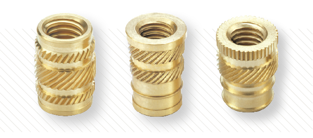
Inserts also provide reusable threads and secure tight threaded joints. Given that Threaded Inserts are generally twice the diameter of screws, the load carrying ability of a joint that uses Inserts is increased by approximately four times the amount as when screws alone are used. Pull-out resistance can be further increased by increasing the length of the Inserts.
Retention within the hole is provided by the plastic conforming to the external features of the Insert. A sufficient volume of plastic must be displaced to entirely fill these external features so that the Insert achieves maximum performance when the plastic solidifies.
This article focuses on the design guidelines for the holes in plastic assemblies that use Threaded Inserts installed by heat or ultrasonic equipment to ensure maximum performance is achieved.
Optimum Design Guidelines:
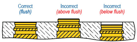
Top of the Insert should be installed as close to flush as
possible with the surface of the plastic.
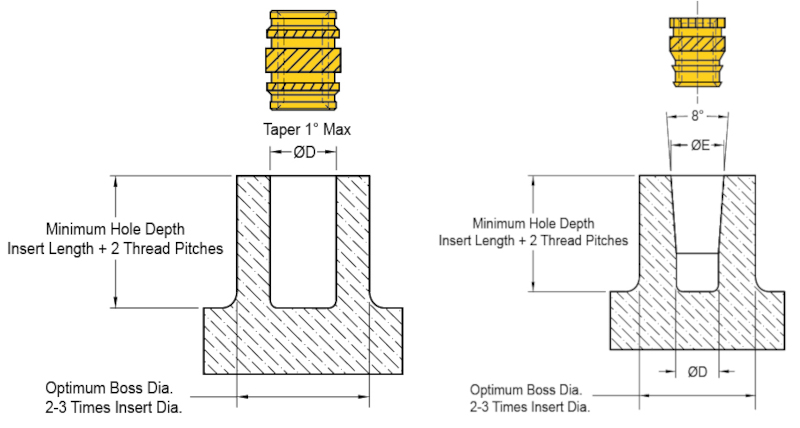
Holes for Inserts installed by heat or ultrasonics should always be deeper than the length of the Insert. The assembly screw should never bottom out in the hole as jack-out would result. The recommended minimum hole depth is the Insert length plus two (2) thread pitches.
The top of the installed Insert should be flush with the surface of the plastic part with maximum protrusion from the host of 0.13mm (.005 inch).
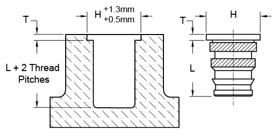
Counterbores are only recommended for Headed Inserts so that the top of the Insert will be flush with the surface of the plastic after installation. The diameter of the counterbore should be 0.5mm (.02”) to 1.3mm (.05”) larger than the head diameter of the Insert. The minimum counterbore depth should be specified as the thickness of the head.
Correct hole size is critical. Larger holes decrease performance, while smaller holes induce undesirable stresses and potential cracks in the plastic. Undersized holes may also result in flash at the hole edge and make the Insert difficult to install.
SPIROL provides the recommended hole sizes for each Insert style in the Inserts for Plastics Design Guide. The recommended holes need to be reviewed if glass / mineral fillers are used.
If the filler content is equal to or greater than 15%, it is suggested to increase the hole 0.08mm (.003 inch), and if the content is equal to or greater than 35%, the suggested hole increase is 0.15mm (.006 inch). For intermediate contents interpolation is suggested.
For straight holes, the taper should not exceed 1° included angle. Tapered holes should have an 8° included angle. Only straight Inserts should be used in straight holes, and only tapered Inserts should be used in tapered holes. Molded holes are preferred over drilled holes. The strong, denser surface of the molded hole increases performance. Core pins should be large enough to allow for shrinkage.
Insert performance is affected by the plastic boss and/or wall thickness surrounding the Insert. Generally, the optimum wall thickness or boss diameter of the plastic is two (2) to three (3) times the Insert diameter with the relative multiplier decreasing as the Insert diameter increases.
The wall thickness has to be enough to avoid bulging during installation, and strong enough to withstand the recommended installation torque of the screw. Poor knit lines will cause failures and reduced Insert performance. Ribs can be added to the boss for added strength.
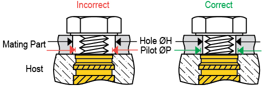
Hole in mating part must be smaller than Insert pilot diameter in host to
prevent the Insert from pulling through the assembly – known as “jack-out”.
The diameter of the clearance hole in the mating component is very important. The Insert, and not the plastic, must carry the load. The hole in the mating component must be larger than the outside diameter of the assembly screw, but smaller than the pilot or face diameter of the Insert. This prevents jack-out. If a larger hole in the mating component is required for alignment purposes, a Headed Insert should be considered.
Given the variety of different plastics and fillers and combinations thereof, consultation with SPIROL Engineering is strongly recommended for each application.
www.spirol.com