
Meshless FEA
Mike McLeod
CAD/CAM/CAE CAD FEAWhat if you could run a full-assembly stress analysis without the painstaking preparation? Canadian startup, SIMSOLID says, no problem.
 Used correctly, finite element analysis (FEA) software is a powerful tool to reliably predict how real-world forces will effect the behavior of parts and assemblies under a load. Its promise is the ability to test multiple “what if” design iterations to arrive at an optimized model that performs up to spec but with a minimum of material.
The problem is relatively few design engineers know how to use FEA effectively. That’s not a criticism. Instead, it speaks to the inherent complexity of the process. Setting up a single simplified part, constraining one region while loading another, is fairly obvious but then so are the results. Certainly nothing an experienced mechanical engineer wouldn’t have known intuitively.
Change that hypothetical to a part with complex geometry, load cases and/or boundary conditions – let alone an assembly with welds, bolts or other tricky connections – and the probability of user error goes up exponentially, as does the set up and processing time. As a result, FEA is rarely used as a design tool. If employed at all, it typically serves to validate a design after it’s entered the final stage before production.
Over the past five to 10 years, engineering software companies have attempted to simplify the process in hopes of popularizing FEA (and hopefully thereby inject some energy into the mature CAD business). Most of those efforts, however, have revolved around streamlining the interface: auto-meshers, model prep wizards and the like. Under the hood though, the fundamentals of FEA haven’t changed much since the software was first developed 60 years ago.
To bring FEA within reach of design engineers, Canadian start-up SIMSOLID Corporation says it has found a way around the frustration and high learning curve associated with traditional FEA. Co-founded by CAE industry veterans, Ken Welch and Victor Apanovitch, the Mississauga-based company says its unique approach to structural, modal and thermal analysis eliminates the need for model simplification and mesh creation. Instead, users can import CAD geometry as is; set loads, material properties and boundary conditions; and receive accurate results, often within minutes, no matter how geometrically complex the part or assembly analyzed.
“It’s a problem I’ve chased throughout my career,” says Welch, who began as an aerospace engineer for the space shuttle program before moving to the software side with FEA companies including PDA Engineering (PATRAN), Rasna (Mechanica), Moldflow and MSC Software. “If you want to democratize CAE, you have to deal with the geometry problem. No matter how well an FEA system is packaged, users still have to simplify the full CAD model’s geometry, remove all the fillets, rounds and holes, and then they have to know how to mesh it. With SIMSOLID, you can analyze the geometry directly. You don’t have to simplify it and there is no mesh.”
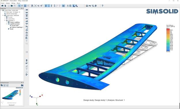
Using SIMSOLID Power edition’s Inertia Relief function, users can analyze a structure that is not constrained and can move as a rigid body, such as this airplane wing.
“The dirty secret of analysis is when you start to talk about assemblies,” Welch says. “FEA was developed to handle parts. When you move to assemblies, you have to build the contacts with exact geometry, such that face 1 exactly meets face 2. That’s often not the case. It may look like they meet but, mathematically, there may be a penetration or a gap between the faces. In traditional FEA, this geometry has to be cleaned up but it’s sometimes hard to find, even with the direct modelers. For us, we can handle ‘dirty geometry,’ by which, I mean these inexact connections.”
Ditching the Mesh
To better understand how SIMSOLID works, it’s helpful to contrast it to traditional FEA. A practical application of the Finite Element Method, the FEA process, at its most basic, breaks down the partial differential equations that describe the physics governing complex objects into mathematically digestible bits, or finite elements, that can be solved numerically. The solution to those manageable algebraic equations can then be melded together to provide an approximate solution to the original, unwieldy problem.
In the context of a part or assembly model, FEA software redefines CAD geometry as a mesh of uniform 3D shapes – a process called “discretization” in FEA lingo. Commonly tetrahedrals or hexahedral bricks, these finite element shapes are each defined by nodes, vertex-like points that connect each building block element to its neighbors. When a load is applied, in the context of the mesh’s boundary conditions and material properties, the FEA software’s solver calculates the extent to which each finite element node would be displaced.
Depending on the element type, a node’s displacement is constrained by its degree of freedom (DOF) – in terms of a node’s translation in the x/y/z planes and/or rotation about its axis. Depending on the extent to which the mesh’s individual nodes are displaced, the FEA system’s post-processor can then interpolate stress and strain and display it visually, commonly as a colorful von Mises diagram.
“In SIMSOLID, the differential equations and variational principals are the same as in traditional FEA,” explains Apanovitch, whose mathematical methods, developed while a professor at Minsk University in Belarus, inform the inner workings of SIMSOLID. “They both have the same symmetrical, positively defined matrices and the same linear algebraic solvers.”
“However, the process of discretization is where the difference starts,” he continues. “SIMSOLID doesn’t break the system into finite elements. Instead, it discretizes the original geometry in a more abstract mathematical way.”
SIMSOLID’s abstract method begins with the import of the original CAD assembly or part model – complete with holes, rounds and other thorny features – which SIMSOLID then automatically splits into arbitrary sub-volumes. Unlike mesh elements, these sub-volumes aren’t required to be uniform in size or shape. They also aren’t defined by nodes, which releases the DOF from being restricted to merely points in space, Apanovitch says.
“Because we don’t have nodes, SIMSOLID’s degrees of freedom aren’t physical and they are not point-wise, like a node” Apanovitch says. “In FEA, geometrical support of a DOF is always a node. In SIMSOLID, it can be a volume, a point-cloud, a line cloud and a mixture of everything.”
It’s this redefinition of the basic ideas of degrees of freedom, Apanovitch says, that forms the crux of SIMSOLID’s innovative approach. By breaking traditional FEA’s dependence on point-wise nodes, SIMSOLID can dispense with the mesh those nodes define. The benefit is that any part or assembly CAD model can be analyzed as is, without a lengthy and time-consuming simplification and meshing stage.
“Geometrically, this is a huge benefit,” he adds. “If you take real world designs, they have so many features and issues that often make FEA infeasible because a mesh cannot be created, even by an automesher. Often, users contact us when they create parts or assemblies they simply cannot mesh.”
Analysis Accuracy
Of course, any analysis method, no matter how innovative or intuitive, is worthless without reliable accuracy. Here again, SIMSOLID diverges from the standard method to provide a less error-prone result.
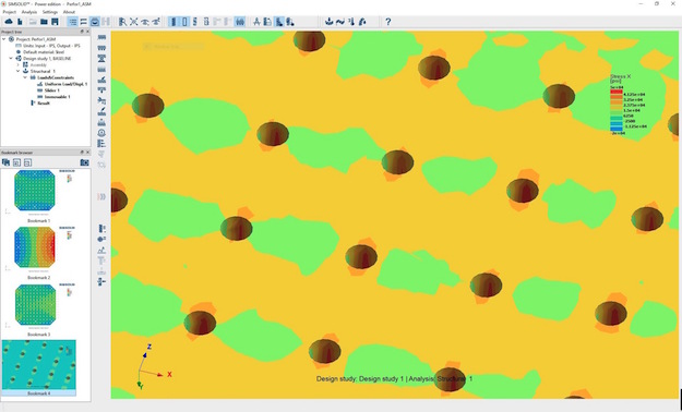
In addition to increasing iteration number, users can fine tune SIMSOLID’s accuracy using the Adapt to Features option that applies more aggressive adaptivity for steep stress gradient areas in local feature areas. Additionally, the Adapt to Stress Concentration option uses higher-level functions for stress concentrations in vicinity of cylindrical holes.
With either method, multiple adaptive analyses are run until the results from using progressively higher density meshes (or higher order polynomials) begin to converge on the same solution, at least within a predetermined percentage. Most FEA packages incorporate h-method, but only one historically, Pro/Mechanica, has relied on p-method.
In contrast, SIMSOLID incorporates analogous procedures for both refinement methods. For example, the software can increase the geometrical density in an area of interest by adding more geometrical supports.
“So, in SIMSOLID, I could add more regions or denser point cloud, or denser point line, which is like the h-version of FEA,” Apanovitch explains. “But, as I mentioned before, the moment you are free to add any function to your approximation space, you can invent whatever you want. Right now, we use five different classes of functions. In FEA, you have only very primitive interpolation polynomials.”

SIMSOLID projects can contain multiple design studies, one of which acts as the baseline. Importing modifications to a part or assembly creates new comparative studies, to which existing baseline material property, connection and analysis definition data are applied.
The end result, Apanovitch says, is that adaptivity, for both h- and p-method, is baked into SIMSOLID’s solution as an automatic procedure. The application itself sorts out how and where to increase the complexity of the model so as to reach convergence quickly and reliably without user input. That reliability holds true even for multi-part assemblies, which can introduce imprecise geometry and connection points that are hard to mesh compatibly.
“SIMSOLID solved this by overcoming the fundamental problem of fuzzy boundaries because, as a technology, it doesn’t require the definition of a well defined boundary that before were required in CAD and FEA,” Apanovitch says. “And because we don’t have meshes, all these issues of assembly compatibility are gone. Second, because we can define DOFs on fuzzy boundaries, all this issue with bad contacts, which is a killer for FEA, is no problem for us. More over, we can handle big gaps and big penetrations. Take for instance a bolt. Because they have threads, they’re always designed as an overlap. We can handle all this perfectly, which is a huge benefit.”
Business Model
While SIMSOLID’s evolutionary leap forward for FEA has been in the works for more than 20 years, the company and its product are still relatively young. When it officially launched in early January 2016, the locally-installed software worked primarily with Jon Hirschtick and company’s latest online CAD venture, Onshape. Users access their Onshape parts and assemblies online where they can export a lightweight SIMSOLID file and import it into SIMSOLID locally for analysis.
In May 2016, the company announced a new SolidWorks plug-in that lets users launch and import models (including assembly tree, part names, material properties, etc) from within the SolidWorks’ interface via a shared memory pipe.
“SIMSOLID’s message is really simple: Get rid of the meshing and work on the CAD geometry directly,” Welch says. “That’s the big difference vs everybody else. We think of FEA democratization as really three things: It’s got to be simple, it’s got to be fast and it’s got to be accessible. That’s been our mantra from the beginning.” DE
www.altair.com/simsolid/