
Modeling an Energy Chain in Autodesk Inventor
By Walt Jaquith, IMAGINiT Technologies
CAD/CAM/CAE Autodesk Imaginit Technologies InventorWhen complex motion gets too difficult, these 3D modeling workarounds can help.
A while back, I was challenged to model the action of an energy chain. These plastic track assemblies capture and organize cables in linear motion systems. They wrap around 180 degrees, reversing direction to allow the cables they protect to follow the machine’s movement without tangling or catching (Figure 1).
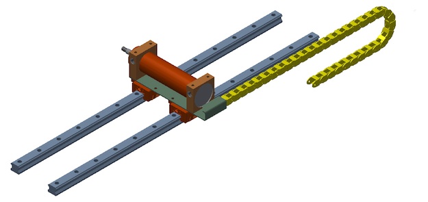
Figure 1: Energy chains are simple mechanisms, but their motion is difficult for a solid modeler to capture.
I found that while Inventor would create the needed relationships, the solver had a difficult time dealing with the complex transitions. I was unable to come up with something that worked reliably, but I did discover a workaround method which works very well, and mimics the behavior of a true energy chain close enough to work for many applications.
Using this method, the chain links don’t actually move around the bend. The chain is broken down into three sections; the upper and lower flat portions, and the curved section which changes the direction (Figure 2).

Figure 2: The layout of the energy chain subassembly, showing the three sections of the chain.
The curved links are constrained together in a rigid arc, and simply move back and forth as the chain articulates. They’re constrained with an offset to the first link in the lower pattern. The offset is calculated so that they are always positioned correctly at the end of the lower pattern of links.
The lower section of the chain is stationary while the upper section moves as the chain articulates. Both straight sections are set up as rectangular arrays, and members are added and subtracted to the arrays to simulate the movement. Rather than moving smoothly, the chain jumps the distance of one link at a time. If the chain is articulated slowly it becomes obvious what’s happening. At faster speeds it becomes difficult to tell the difference.
The math that drives it all is fairly simple, and uses three main user parameters (Figure 3).
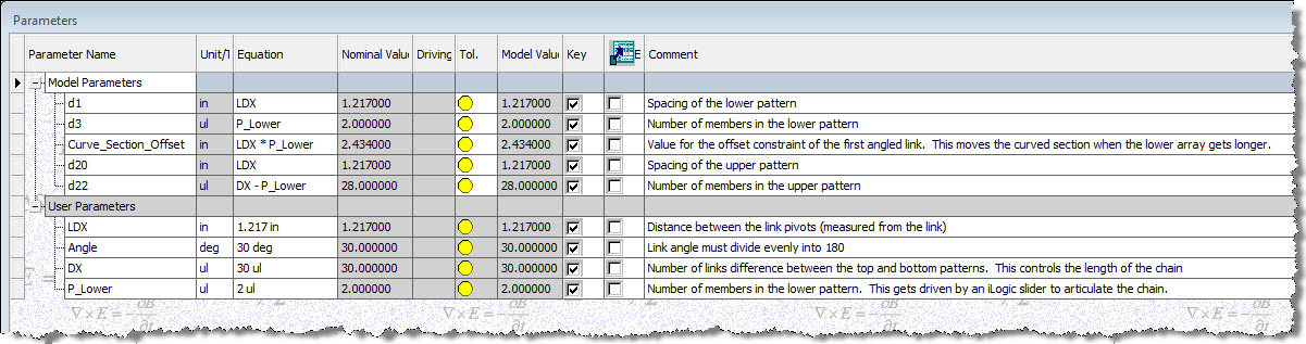
Figure 3: The parameters dialog box for the energy chain assembly, filtered to show only the key parameters.
The most important is LDX, which equals the distance between the link pivots. This controls the spacing of both the patterns, and is also multiplied by the number of components in the lower array to provide the offset for the curved section of the chain. A unitless parameter named DX controls the overall length of the chain by designating how many more links the upper pattern has than the lower. Finally, P_Lower controls the number of links in the lower pattern. This is the parameter, which gets driven to articulate the chain.
When P_Lower is changed from 2 to 3, three things happen: First, a member is added to the lower pattern. Then the curved end assembly is moved out to make room for that new link. Finally, one member is subtracted from the upper pattern. The visual effect is that the whole chain moves, looking much as it would when articulating on a real machine.
One easy way to drive the P_Lower parameter locally is with a slider on an iLogic form. Set the minimum to 2 and the maximum as needed. The energy chain can then be articulated through its range by moving the slider. The next step is to insert the energy chain assembly into a machine assembly and link it to the motion of the machine. This involves a simple iLogic rule in each assembly. In my example, I have an assembly with a bracket set up on linear rails. Its position is controlled by a user parameter named “Carriage_Drive”. The chain subassembly has been inserted into this assembly and renamed to “EC-01:1” (Figure 4).
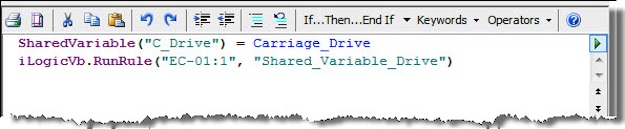
Figure 4: The iLogic rule in the top level assembly. This rule creates the shared variable which allows the energy chain subassembly to be driven when the carriage moves.
The rule in the main assembly makes Carriage_Drive equal to a shared variable called “C_Drive”, and then runs the rule in the energy chain subassembly (Figure 5).
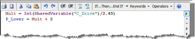
Figure 5: The iLogic rule in the energy chain assembly. The ratio between the two assemblies will vary according to the distance between the link pivots.
The rule in the subassembly performs some math to deal with the ratio between the travel of the carriage and the articulation of the energy chain. The shared variable’s value needs to be divided by a factor (in this case, 2.45), and converted into an integer. It can then be used to drive the chain sub’s P_Lower parameter, so that the energy chain follows when the carriage in the main assembly is moved (Figure 5).
Back in the main assembly, the Carriage_Drive parameter can be driven however desired. As the carriage moves, the energy chain will move with it (Figure 6).
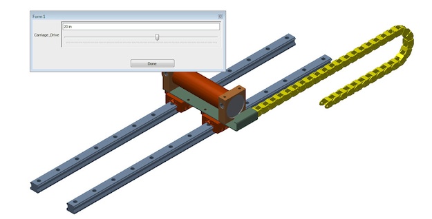
Figure 6: Driving the carriage in the top level assembly. The energy chain subassembly will follow as the carriage moves.
It’s not perfect; the carriage moves smoothly while the chain jumps one link at a time. In this example, I got creative and hid the upper end of the chain so the discrepancy is not so apparent. If you are exporting video of the machine’s motion, the faster the carriage moves the less apparent the jumping will be.
If you need smooth, realistic motion in your energy chain, you will have to work carefully with your assembly constraints. The method I tried involved a reference part, which described the path of the chain, and lots of transition constraints. I did get it working at one point, but it was a lot of effort both for me and for my machine. If your needs are less precise, this workaround may get you there.
www.imaginit.com
Walt Jaquith is an applications expert at IMAGINiT Technologies. Check out more Inventor modeling tips on the IMAGINiT Manufacturing Solutions Blog