
Solid Edge: Working constraints in synchronous technology models
By John Pearson, Design Fusion
CAD/CAM/CAE Design Fusion John Pearson Solid EdgeAutomating dimensions and 3D models in Solid Edge's Synchronous Technology environment
There seems to be some confusion amongst some users regarding the ability to constrain synchronous parts. The confusion has even lead to inaccurate information being perpetrated as truths, by some competitive product’s resellers.
So I’d like to set the record straight and clear up several misconceptions. First and foremost, you can constrain synchronous models. Secondly you can use the variable table to drive synchronous models. And last, but not least, you can automate synchronous models through custom programming or a configurator.
Ordered constraints
To understand how this works, let’s fist look at an ordered part. Below is a sketch for a part that I wish to model. Notice that I have fully constrained the sketch.
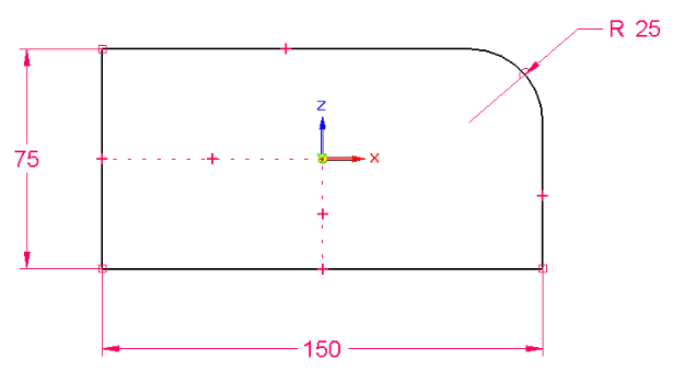
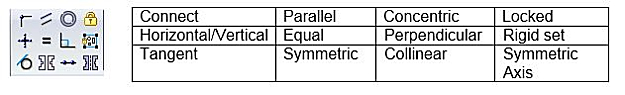
The sketch has zero degrees of freedom, so I can predict what will happen when I make a dimensional change to any of the 3 values. I control part of the sketch with geometric constraints, which include the following 2D relationships:
When I use the sketch to create a model, the sketch becomes the parent of the solid model, as shown below:
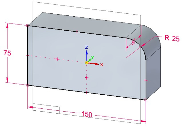
This model is considered constrained because it is controlled by the fully constrained sketch and the depth dimension, added during the extrusion command. Notice that we can go into the variable table and apply specific names to each dimensional variable.
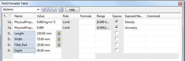
I can now drive predictable model changes using the variable table. Furthermore I can link the variable table to an Excel spread sheet, a custom program, or a configurator to drive model changes.
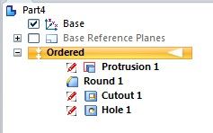
When a variable is changed, the system first re-calculates the sketch and ensures that the sketch is still a valid profile. It then moves on to the child of the sketch, in this case the model, and re-computes the model to ensure that we still have a valid model. If additional features were added to the model (like a round or chamfer) it would continue to re-compute the next feature(s) until it has completed the feature tree list. For small models with few features, this is a rapid process. However, the more features an ordered model has in it, the longer the re-compute time will take.
Synchronous constraints
Now let’s make the same part in the synchronous mode. We start by making a sketch, as shown below:
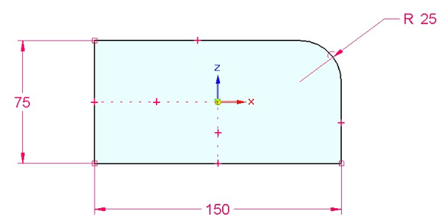
Notice that I can fully constrain the sketch in synchronous mode. The difference here is that when I create the solid, only the dimensions are migrated to the 3D model. The 2D geometry and 2D geometric constraints are left in the Used Sketch header on the PathFinder. In other words, no parent child relationship is created between the sketch and solid, and the 2D dimensions are converted to 3D driving dimensions on the model, shown below:
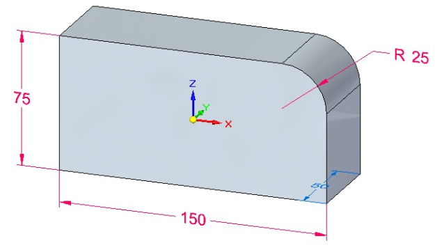
Notice that 3 of the 4 dimensions are red in colour, while the depth dimension is blue. A red colour means that the dimension is locked and can only be modified by a direct edit of that dimension. Let’s make the fourth dimension locked as well.
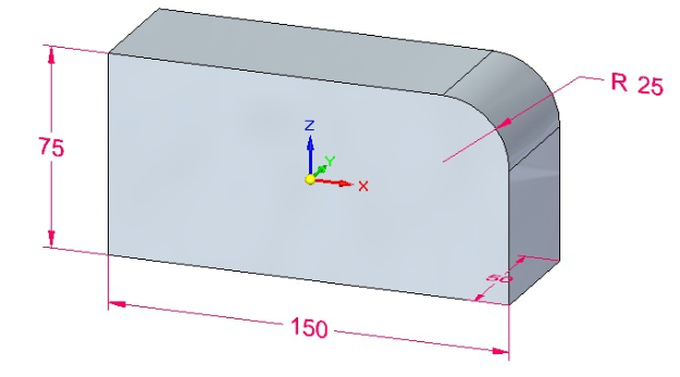
So now we have the dimensions fully constrained or locked. What about the geometric constraints? Since the 2D geometric relationships have not been transferred to the model, a lot of users become concerned that the model is no longer fully constrained. They are partially correct. Let’s take a closer look at the model.
By the nature of the solid, we can make a few assumptions.
1. The connect relationships will be maintained at the model level. Why? Because if they are not we no longer have a solid.
2. Synchronous edits use Live Rules, and Live Rules will maintain most of the pre-existing geometric situations. For example, if you attempt to change the values in the part, default Live Rules will keep the walls in their current horizontal/vertical position.
3. Synchronous will only analyze the effected faces in any move. Therefore it only has to re-compute faces affected by an edit.
Even with these assumptions, there admittedly could be some un-expected results if you are using this model in a custom program or configurator. So how do we eliminate potential un-expected results? We use 3D geometric relationships.
Persistent (3D) relationships
Looking at the original sketch of our model, you’ll notice that the sketch was centered on the base coordinate system. I can do the same with the model by using the horizontal/vertical persistent relationship command. I’ve placed these relationships in the model, shown below. Notice that they also are listed under a Relationship header in the PathFinder.
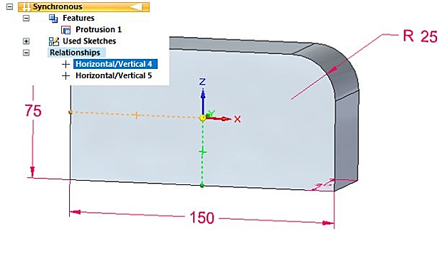
Simply by placing these two relationships, I now have predictability in any dimensional edit. I can now set this synchronous model up in the Variable Table.
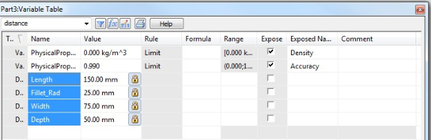
I can now drive predictable model changes using the variable table. Furthermore I can link the variable table to an Excel spread sheet, a custom program, or a configurator to drive model changes.
For more complex models, synchronous offers even more 3D geometric relationships.
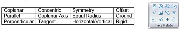
Notice the striking similarity between our 3D geometric relationships and our 2D geometric relationships. There is however one big difference. I only have to use the relationships that I need to control my model. Because synchronous technology only re-computes faces that are affected by an edit, I may not have to fully constrain a model.
Some will argue the fact, but the truth is the majority of ordered models that I see from customers are under-constrained. Because of the parent child nature of ordered modelling, this could be, and often is a problem when editing ordered part models. If you doubt this statement, go back to your database and open some of your existing models. Under the Solid Edge options > General tab, turn on the ‘Indicate under-constrained profiles in PathFinder.
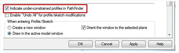
If a red pencil icon appears anywhere in the PathFinder, you have under-constrained features.
This is a real concern in ordered modelling, but not in synchronous modelling. As you’ve seen, the nature of synchronous modelling puts the focus on only what’s being edited. As you have also seen, a synchronous model can be fully constrained if necessary. Either way you can have complete predictability of the model and use it in configurators or custom programs.
So, as I stated at the start of the blog article, you can constrain synchronous models. You can use the variable table to drive synchronous models. And you can automate synchronous models through custom programming or a configurator. Anyone who tells you different has not been properly trained in synchronous modelling or works for a competitive software package.
For more Solid Edge tips and tricks, check out Designfusion’s blog.
www.designfusion.com
 John Pearson is a Senior Technical Trainer and Application Specialist at Designfusion. He has over 24 years’ experience in the CAD/CAM industry, is a Certified Adult Trainer and has taught evening CAD courses at colleges in Ontario. He is also a major contributor of articles on the Design Fusion blog.