Splitting Parts with Parts in Autodesk Inventor
By Chris Griffith, IMAGINiT Technologies
CAD/CAM/CAE Autodesk CAD Chris Griffith Imaginit Technologies InventorHow to create a complex surface based on a part to split or trim another part.
Ever had to trim a part with another part, but the second part was just too complex to use the extrude tool with? These issues have popped up and often leave users confounded, but there is a very simple solution to this dilemma. In this example, we will be using the Split tool to trim the part, we will be creating a surface based on the complex part and using it as the split tool.
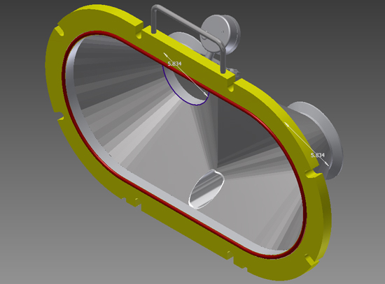
Here we have a pipe that is inserted through a hole and it needs to be trimmed flush to the inside of two sheet metal parts for flow purposes. The problem lies in the complex nature of the interior of the manifold and it poses some challenges in creating a flush end on the pipe.
Split, the Basics
![]() For those of you not familiar with the Split tool it is located on the ribbon in the Modify Panel, and is a modification tool that allows the user to:
For those of you not familiar with the Split tool it is located on the ribbon in the Modify Panel, and is a modification tool that allows the user to:
- Split the face of a part
- Remove a section of a part
- Split a part into multiple solid bodies
The command works by using a line, a plane or surface as a splitting tool, as shown in the examples below.
With a Line
With a Plane
With a Surface
Setting Up the Split
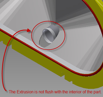
We have a model with piping entering the internal area of the assembly. For our purposes we need these pipes to be flush with the inside of the model. Any ordinary means of doing this in Inventor will not lead us to the desired result, so we must become a little more creative and use some of the features that, as mechanical users we may normally not use. The following image shows us that an extrusion removing material does not produce the geometry we want. The result we obtain after completing the cut is not the flush part that we wish to have. Let’s jump in to solving this problem, and learn how beneficial slicing with surfaces can be.
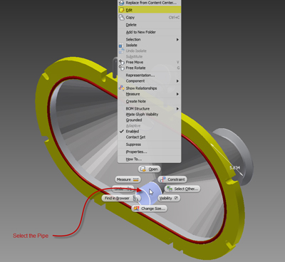
Start by selecting the pipe and editing it in the assembly. Then go to the 3D Model tab > Modify Panel > Copy Object command. This will open the Copy Object dialog box allowing us to copy surfaces to use for our split.
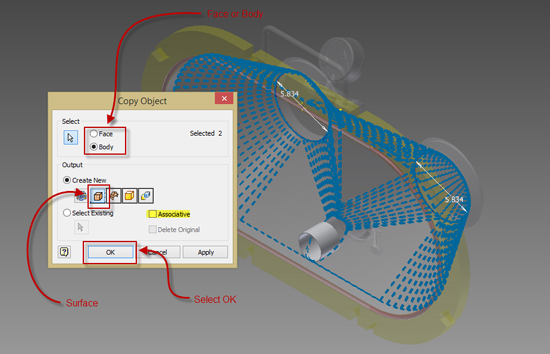
In the Copy Object Dialog Box we will select Face or Body, I selected body to keep it simple. (Selecting face will require picking each face that that touches the item to be trimmed). We will then select Surface and select the items we use to trim our pipe.
Note: Associative can be checked or unchecked. If checked the copied surface geometry is linked to original part.
Select OK to finish the command.
Once the command is completed you will notice that the two copied surfaces will show up in the model browser, the next step will be to open our part to make creating our slicing surface much easier. By following these steps only the surfaces you have created will be left.
Next we will create our surface that will be used as a trimming or split tool. We will be using the Boundary Patch command located in the 3D Model tab > Surface Panel to achieve this. In the Boundary Patch Dialog box , start selecting the edges that will form the cutting surface outline. Once they are all selected the Boundary Patch should show up as a preview and we can select the Apply or OK button to finish the command. We will then use the Extend Surface command located in the 3D Model tab > Surface Panel to ensure a proper slicing surface. Select ok to finish the command.
We can now unsuppress our Solid(Extrusion 1) in the Model Browser and use the Split tool located in the 3D tab > Modify panel.
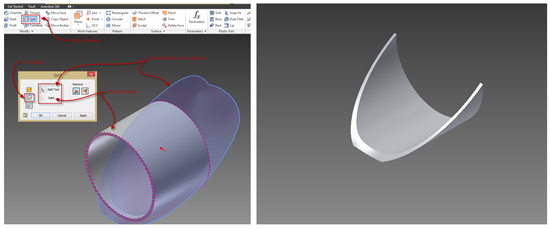
In the Split dialog box, select the split tool, the solid, the Trim Solid button and the direction to remove material from and click apply or OK.
The result will be a part split to match the contour of the surface we created, the pipe is perfectly trimmed to the sheetmetal interior. Repeat the split command as necessary to create a perfect flush part.
Chris Griffith is an Manufacturing Applications expert at IMAGINiT Technologies, who provides standard, custom and advanced AutoCAD and Inventor training. Check out more Autodesk software tips on IMAGINiT’s Manufacturing Blog.


