Using the Improved Drawing View Wizard in Solid Edge ST6
By John Pearson, DesignFusion
CAD/CAM/CAE CAD Designfusion John Pearson Solid EdgeNew drawing method utilizes the toolbar approach which is found in most Solid Edge commands.
As more and more users migrate to Solid Edge ST6, I am receiving more calls asking about the Drawing View Wizard. There was a major overhaul in ST6, but do not panic, for you can reset it to behave as it did in previous versions. The new method utilizes the toolbar approach which is found in most Solid Edge commands, where the old way uses the wizard approach.
How to set the drawing view command to the wizard method
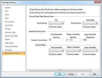
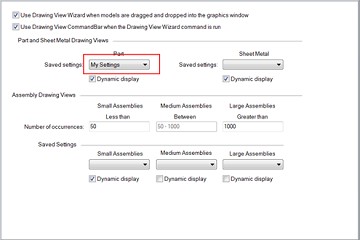
A new tab has been added to the Solid Edge options in the Draft environment. The tab is entitled Drawing View Wizard, and allows you to define some default settings.
These settings define how and when the Drawing View Wizard runs with respect to the model type selected. If you wish to use the old style wizard simply un- check the following toggle:
To learn about the other settings, click on the Help button. The help documents have a complete breakdown of all the other settings.
Using the new Drawing View Wizard method
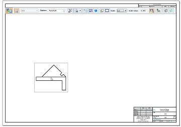
If you leave the previously mentioned option checked, you will use the new simplified workflow for placing a drawing view. The simplified mode reduces the number of steps required to generate drawing views. It omits the wizard dialog boxes and instead displays the View Wizard command bar at the drawing view placement step. This is the default mode for the View Wizard command.
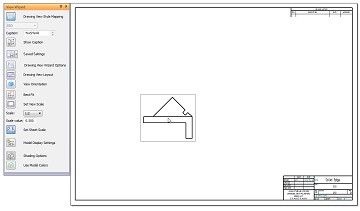
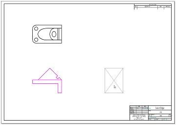
In the image above you can see that after I selected the part file and I am given a Front view of the part, attached to my cursor, along with a command bar. In this example I am using the horizontal command bar. I could also use the vertical command bar as shown in the following image.
Note: You can choose whether you want to use vertical or horizontal command bars in the Solid Edge options, under the Helpers tab.
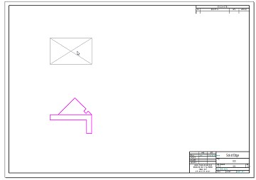
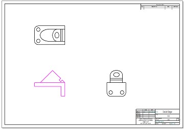
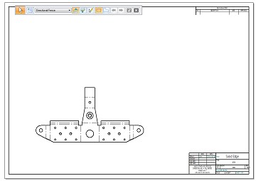
I can place this view on my draft sheet and I am immediately put into the principal view command. This allows me to place alternate companion views based on the position of my cursor. For example, if I want a Top and Right view, along with the Front view, I simply move my cursor up and click for the Top view.
I can then move my cursor to the right and click for the Right view.
To exit the command I hit the Esc key, on the keyboard.
Preselecting layouts and presetting options
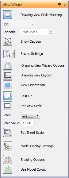
Before I place any views I can preselect layouts or preset some options. All these options are on the command bar. The image below is that of the vertical command bar. I use this for training because it shows the option names.
As you can see there are over a dozen options here. I will focus on the 6 most common, but a description of all the options can be found in the Solid Edge Help section.
This option allows you to specify content and display options based on whether the drawing view is an assembly, part, or a sheet metal model. When you select it the following dialog appears:
- For Part or Sheet metal files.
- For an Assembly file.
For those of you familiar with the old Drawing View Wizard, you will recognize these dialogs as the first dialogs that appear. All the options that you are used to are still here.
This option allows you to select additional views to place along with the primary view. You also can change the orientation of the primary view. When you select it the following dialog appears:
Once again this dialog should be familiar to existing Solid Edge users. It is a combination of the 2nd and 3rd dialogs of the old Drawing View Wizard. Here you pick your primary view and the companion views. Note that the primary view can be a preset view or a custom view.
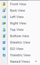
This option allows you to change the view orientation before you place it. For example, if you just wish to place a single view, you can control the orientation by selecting this option and choosing from the following drop down list:
You can use this option if you don’t plan to add companion views.
Best Fit, Set View Scale, Scale List and Scale value
These options allow you to control the size of the view that you are placing. They are identcal options that you would find in the previous Drawing View Wizard command, and are used the same way.
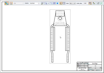
This is a new and very useful option to ST6. It allows you to save your layouts for reuse in other draft files. For example, if I always place a flat pattern of my sheet metal parts, I can place my first layout and save it. To do this I do the following steps:
1. Start the Drawing View Wizard command and select the file that I want to place onto the draft sheet
2. Set the Flat pattern option.
3. Select the scale that I want to use. But do not click to place the view yet.
4. In the Saved Settings dialog I name this layout as Flat and hit the save icon.
5. Place your view.
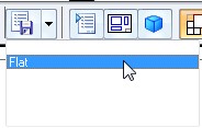
The next time I run the Drawing View Wizard, with a Sheet Metal part that contains a flat pattern, I just have to select “Flat” from my saved settings.
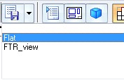
Following the same steps I could save another layout showing the Front, Top, and Right view for the same model, and save it as “FTR_view”. The next time I run the Drawing View Wizard on a Sheet Metal part, I could select from either layout.
Note: I find saving layouts easier if you always start with a new draft file, per layout. There are a couple of things to note here:
- To use a saved setting, that setting has to be selected before the drawing view is placed on the drawing sheet.
- Your saved settings are based on model type and model size. For example if I place a part file, I will not see the Flat or FTR_view saved setting, because I created them using a Sheet metal part.
- Your saved settings can be predefined per model type and model size (for assemblies) on the Drawing View Wizard tab (Solid Edge Options dialog box).
Items stored in the saved settings:
- All properties from the properties tab.
- View orientations
- Custom orientations
- Best Fit
- Set View Scale
- Shading Options
- Edge Colors
Saved Settings file will be created in the reports directory called DraftWizard.txt.
Once you’ve created a list of saved settings, I believe that you’ll find the new approach more efficient and easier to use. But if you still prefer the old method, you can still use it.
www.designfusion.ca/blog.html
 John Pearson is a Senior Technical Trainer and Application Specialist at Designfusion. He has over 24 years’ experience in the CAD/CAM industry, is a Certified Adult Trainer and has taught evening CAD courses at colleges in Ontario. He is also a major contributor of articles on the Design Fusion blog.

