What’s new in Solid Edge ST6 — Part 2
By John Pearson, DesignFusion
CAD/CAM/CAE CAD Designfusion John Pearson Solid EdgeLatest release of Solid Edge features enhancements to sheet metal, assembly and drafting design functions.
In part 1 of this article, I had started to discuss what was new in Solid Edge ST6, as introduced to us at Solid Edge University 2013. I left off with mentioning the new enhancements in surface modeling. So let’s continue with what’s new in Part and Sheet Metal modeling.
ST6 Part and Sheet Metal Design
Improved Steering Wheel – now has 3 directional axes to eliminate the annoying need to always flip the steering wheel.
Improved solution manager – including color control, something I had requested for some of our color blind users.
Faster revisions with synchronous technology – Include or exclude edges of peer parts during creation. Added exclude interior loops or use only interior loops, to the Extrude planar face option from ST5.
Better reuse with synchronous technology:
- More robust rectangular and circular patterning.
- Pattern recognition allows count and instance editing of imported patterns.
- Partial round delete with end capping.
- Dimensioning chamfered edges uses virtual vertices.
Create stamped sheet metal parts with a single command – emboss a tool or punch into a sheet metal part.
Stiffen parts by adding features across bends – add beads, dimples, louvers, emboss features across bends
Sheet Metal Features on Parts – sheet metal features can be placed on regular ordered parts of uniform thickness without having to transform the part to sheet metal. This provides an especially efficient method in stamped metal design.
Again, there are many other enhancements in Part modeling which will benefit all users.
ST6 Assembly Design
Solid Edge continues their dominance in working with large assemblies. Along with some nice enhancements to PathFinder Indicators and Physical Properties, here are my favorite improvements:
Assembly occurrences can now be used for inputs to Boolean operations – No inter-part copy of the geometry is needed and multiple tool body components can be selected (see previous blog article).
Faster display – New display capabilities speed pan/zoom/fit by up to 2 times.
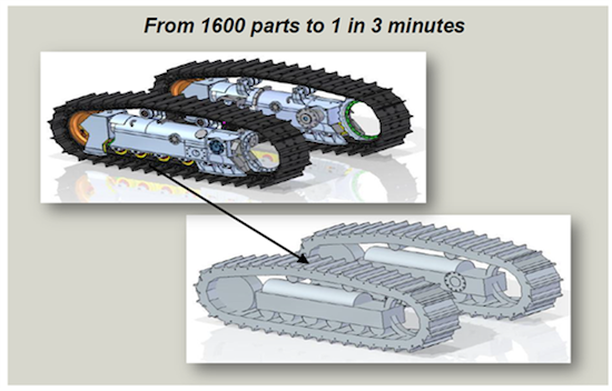
Complete overhaul of simplify assemblies:
- New environment for creating user defined simplified representations.
- Enclose component automatically encloses components with rectangular or cylindrical solids.
- Duplicate body speeds simplification of copied or patterned components.
- Goal is to simplify models for effective design of 1 Million+ parts.
Create In-Place Enhancements – moved to optional QuickBar with better control over placing the origin.
Synchronous Assembly Modeling Peer Edge Locate – allows for improved key-point selection when modeling in the Assembly.
Plus several new enhancements to synchronous commands have been made while a user is in-place activated into a part or sheet metal file from an assembly.
ST6 Drafting
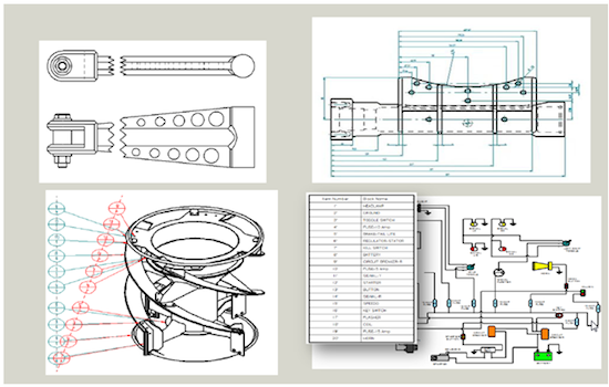
Two of the most exciting enhancements in Solid Edge ST6 appear in the Draft environment. When the following was demonstrated they received an enthusiastic round of applause from the audience at SEU2013.
Alignment control
- Align annotations with a linear, rectangular or fitted shape.
- Reposition the annotations by dragging the alignment shape.
Dimension auto-arrange
- Clean up messy dimensions with a single mouse click.
- Select dimensions by fence or by drawing view.
- Creates and aligns dimension grouping.
Some other notable changes in drawing production are:
- Faster zoom/pan, and hatch display with large 2D drawings.
- Auto-constrain 2D elements during drag-modify.
- Retrieve slot feature centerlines.
- Partial bolt hole circles.
- Simplified drawing view wizard.
- Shortcuts and easier sheet tab creation.
- Edit tables in place.
- Better editing of embedded documents.
- Drawing views are now displayed before placement.
- Derived break lines from one view to another.
- Align any drawing view with key-points or drawing view centers.
- 2D directional fence select: left for overlapping, right for inside locate to.
- Create tables from placed blocks on schematic drawings.
These enhancements, and more, continue to make Solid Edge’s drawing capabilities the best on the market.
Help for SolidWorks refugees
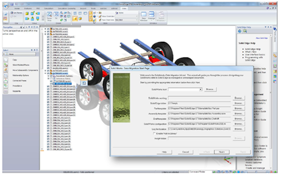
One other noteworthy feature, added to Solid Edge ST6, is the new SolidWorks migration tool. Siemens is going after the SolidWorks customers who are concerned about the kernel change and loss of legacy data. This tool, combined with some other enhancements, will allow the SolidWorks user to:
- Protect their investment in design.
- Get the power of synchronous technology.
- Maintain speed and reliability with Parasolid.
If you are a SolidWorks customer and are concerned about the ongoing changes and mixed messages from Dassault Systemes, Siemens is willing to help you transition to Solid Edge, while protecting and reusing your legacy data.
Solid Edge ST6
As mentioned at the beginning of the article, I have only scratched the surface of what’s new in Solid Edge ST6. I did not even mention the enhancements in the simulation package, standard parts, framing, or data management. I will attempt to expand on the improvements in future blog articles.
But I felt it important to give an overall account of Solid Edge ST6, as presented at SEU2013. I have worked with Solid Edge for over 10 years now and I am truly impressed with how the development team continues to listen to the actual customers. Solid Edge ST6 enhancements have truly been driven by the customers. The 3 core values for this release were to:
- Accelerate design for faster time to market.
- Faster revisions for higher repeat business.
- Better reuse for lower development costs.
Siemens has done a great job at meeting these core values with Solid Edge ST6. Judging by the excitement at SEU2013, this looks to be a great release with customers eagerly awaiting the arrival of Solid Edge ST6. The release date has not been finalized yet, but the general consensus is that customers can expect to receive their copy sometime in August 2013.
 John Pearson is a Senior Technical Trainer and Application Specialist at Designfusion. He has over 24 years’ experience in the CAD/CAM industry, is a Certified Adult Trainer and has taught evening CAD courses at colleges in Ontario. He is also a major contributor of articles on the Design Fusion blog.


