Common mistakes made by new Solid Edge users – Part 1
By John Pearson, Design Fusion
CAD/CAM/CAEHow best to leverage direct modeling tools in Solid Edge’s ordered, parametric mode.
 Over the next few blog articles, we will be focusing on some of the more common mistakes made by novice, or self-taught users of Solid Edge. Along with the mistake, we will illustrate how to avoid these mistakes or show more efficient ways to use the software. It is our hope that these articles will help you become a better user of Solid Edge and speed up your design process.
Mistake #1: Not using, or not aware of Direct Editing in Solid Edge Ordered modeling.
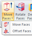
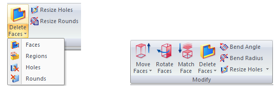
A common question or criticism from users is; “There’s got to be an easier way to move or modify a body in the ordered paradigm?” Often this comes from users who have imported a solid from another CAD package and they want to center it at (0,0,0), or they need to modify the size, etc. Many users are unaware of the Direct Editing tools that were added years ago, in V17. These tools are found on the Home Tab>Modify group, in the Ordered paradigm.
These commands allow you to move, offset, or rotate faces and bodies.
You can also delete faces, regions, holes, and rounds. Plus you can resize holes and rounds, or bends in sheet metal.
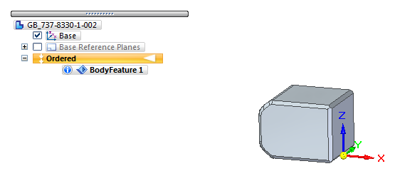
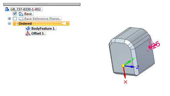
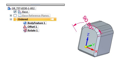
Let’s look at an example of how these commands can assist you. Below is an image of an imported part file. Notice there is no history in the PathFinder, and that we are in ordered modelling.
In this example I have to do 3 changes.
- Make the part 0.125” larger on all sides
- Rotate the part 90 degrees and center the front face on (0,0,0)
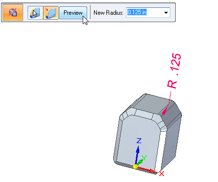
- Make all the rounds 0.125”
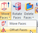
Here are the steps to do these modifications. First I select the Offset Faces command.
I select the Body option from the selection filter.
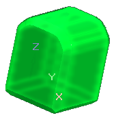
I select the body and accept it.
Next I enter in the offset distance and, using my cursor, point and click to define the direction of the offset.
The result is a part 0.125” inches larger on all sides. Notice that an Offset feature has been added to the PathFinder. I could also edit the offset dimension visible on the screen.
Finally I hit Finish to complete the command.
Now I want to rotate and re-position the part. First I select the Rotate Faces command.
I select the Body option from the selection filter.
I select the body and accept it.
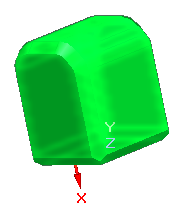
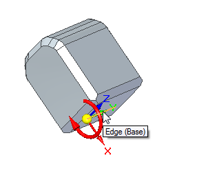
Now I need to define an axis of rotation. From the command bar, I select “By Geometry” and then I pick the Y-axis for my axis of rotation. Notice the direction arrow head, showing the positive direction of rotation.
I rotate the body 90 degrees.
Notice the added feature and the editable on screen dimension.
Finally I hit Finish to complete the command. I then select the Move Faces command.
Once again, I select the Body option from the selection filter.
I select the body and accept it.
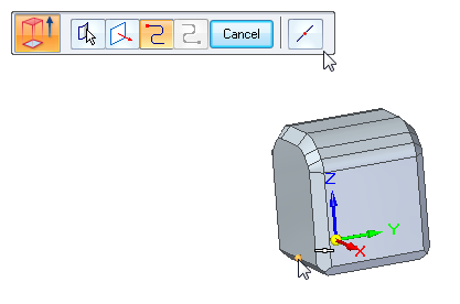
I next have to tell the system how I plan to move the part. In this example I will use the ‘In Plane’ method. I select this from the command bar.
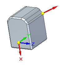
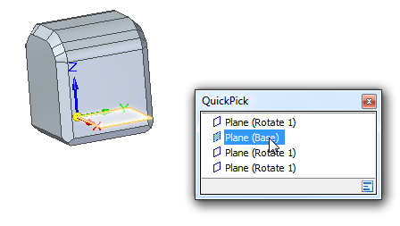
I then select the XY plane, as shown below, telling the system which plane I’m moving in.
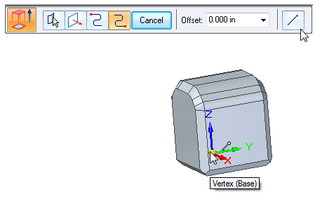
I now have to define the start (or from) point and the destination (or to) point. Here I select the midpoint option and select the front midpoint as shown.
For the destination point I select the endpoint option and select the base coordinate system’s origin.
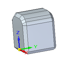
I have now repositioned my part.
Finally I hit Finish to complete the command.
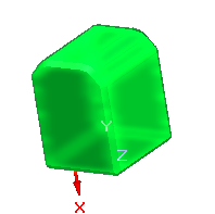
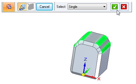
The last step, in this example, is to make sure that my 4 rounds are set to 0.125”. To do this I select the Resize Rounds commands.
I select the 4 rounds from the part.
Notice that the rounds are currently 0.250”.
I enter in 0.125” and click on the Preview button, to get a preview of the changes.
Finally I hit Finish to complete the command.
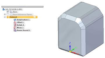
Notice that the PathFinder has tracked all the changes. These are features that can be edited or deleted if necessary for future changes. The result here is a quickly modified ordered part that was imported from another CAD system. You can also use these commands on ordered parts made inside of Solid Edge. Here I’ve illustrated only a few of the modified commands. To learn how to use all the Direct Edit commands you can view the Help section of Solid Edge or attend one of our Advanced Modelling courses. Visit our technical training page to learn more about our advanced courses.
www.designfusion.ca
For more Solid Edge tips and tricks, check out Designfusion’s blog.
www.designfusion.com
 John Pearson is a Senior Technical Trainer and Application Specialist at Designfusion. He has over 24 years’ experience in the CAD/CAM industry, is a Certified Adult Trainer and has taught evening CAD courses at colleges in Ontario. He is also a major contributor of articles on the Design Fusion blog.
Print this page
Advertisement
<


