Master the Solid Edge ST Steering Wheel
By John Pearson, Senior Technical Trainer and Application Specialist, Designfusion
CAD/CAM/CAE CAD Design Fusion John Pearson Solid Edge steering wheelThe drag-and-drop Synchronous Technology “steering wheel” interface can be confusing, but getting a handle on it pushes model design into the fast lane.
Many traditional users have expressed some concern over the use of the steering wheel in synchronous technology. They find it complicated or cumbersome to use. However, once they receive proper training they all agree that it is a powerful and useful tool that is really quite easy to use.
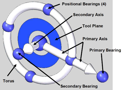
The basics of the steering wheel allow the user to move faces in a linear, rotational or freeform move, similar to the Drag Component command in the assembly environment. The primary and secondary axes allow you to perform linear moves. The torus allows you to perform rotational moves. The tool plane allows you to perform freeform planer moves. With a little knowledge you can quickly and easily move or rotate faces or face sets as required. The notes below are what our trainers hand out, in our courses, and illustrate a few simple ways to control and position the steering wheel.
Positioning the steering wheel
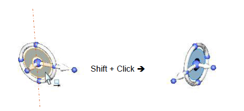
When you want to rotate the steering wheel 90° on an axis that is NOT defined by the primary axis of the steering wheel, hold down the Shift key and Click the small blue plane inside of the steering wheel.
• Shift + Click the Tool Plane will flip the steering wheel 90° about the axis NOT aligned with the primary access.
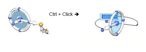
• You can also Ctrl + Click the primary bearing knob at the end of the primary axis and key-in an angle.
When you want to rotate the steering wheel 90° on an axis that is defined by the primary axis of the steering wheel, pick the bearing knob on the secondary axis of the steering wheel and drag to rotate.
• The steering wheel will snap to 90°.
• You may also Shift + Click the bearing knob at the end of the secondary axis and key-in an angle.
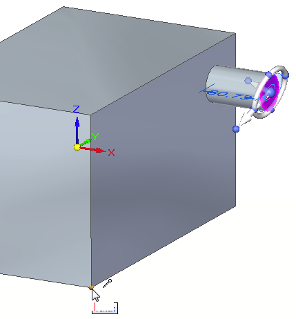
Once you get the steering wheel in the desired orientation, Shift + Click the origin of the steering wheel to relocate it.
• No need to continue to hold down the Shift key after clicking
• It will not flip orientation.
• Secondary axis will not realign to an edge
Changing the Primary Axis Vector
You can change the direction of the primary axis by doing one of the following:
• Click on any of the 4 positional knobs.
• Click on the primary bearing, hold the LMB down and align with any keypoint.
For more information on the steering will you can check out the online training section on ‘Moving and rotating faces’ or attend one of our synchronous training courses.
If you are a regular follower of Design Fusion’s blog, you may recall the article on training, where it mentioned that one hour of instructor lead training is equivalent to 16 hours of trying to teach yourself.
For more training information please visit the Design Fusion training site.
www.designfusion.com
 John Pearson is a Senior Technical Trainer and Application Specialist at Designfusion. He has over 24 years’ experience in the CAD/CAM industry, is a Certified Adult Trainer and has taught evening CAD courses at colleges in Ontario. He is also a major contributor of articles on the Design Fusion blog.


