Solid Edge ST5: Editing Part/SM Operations in Assembly
By Cory Goulden, Design Fusion
CAD/CAM/CAE CAD Designfusion Solid EdgeLocate, select and edit features without having to enter models directly in Solid Edge ST5.
In ST5, you can now perform edit operations, from the assembly environment, without first in-place-activating to enter the model directly. Things you can do:
- Locate, select and edit of ordered features
- Edit synchronous procedural features
- Delete synchronous face-sets and ordered features
- Move face-sets (sync feature) in synchronous parts
Let’s take a look!
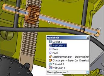
Firstly, ordered features are now selectable via the Face Priority select option. (Remember hotkey combo is CTL + Spacebar)
Notice in the example below that “Protrusion 1” is available from the Quickpick options in assembly now.
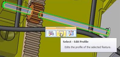
Once selected, “Protrusion 1” has its options displayed for going directly into the features parameters.
Select whatever you would like to edit and SE will take you directly there. Once complete, just close and return. This will take you back to where you were in the assembly.
This saves time from previous versions by allowing you to go directly to what you want to modify and brings you back to the assembly reducing the number of mouse clicks.
Editing synchronous procedural features from the assembly level does not in-place-activate the user into the part. Procedural features are things such as Patterns, Thin wall, Helix, Hem, Dimple, Louver, Drawn cutout, Bead, Gusset, and Etch. These are editable directly in the assembly.
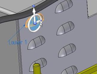
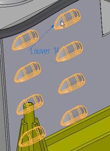
Using Face Select again, “Louver 1” is selected.
The handle for the procedural features shows up. If selected we are presented with the following options.
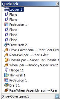
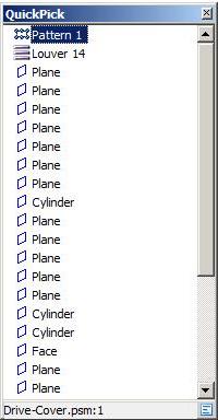
Also, if we were to select the adjacent lover we would be presented with the following options:
Notice that the option to edit the pattern is there. I know what the usual next question would be: “How would I know how to edit the parent of the pattern?” Notice the option for “Louver 14”; if you were to select it, you would be presented with the same options as previously mentioned.
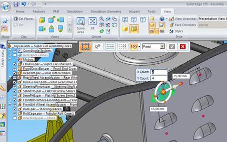
We select “Pattern 1” and now we can modify the parameters that define the pattern.
Once selected, click on the PMI callout “Pattern 2 x 4” and we will get the following options:
Notice we have not left the Assembly environment. One thing to note about this type of editing: Procedural Feature profile editing requires in-place-activating first. Also, there is no access to the profile handle from within the assembly.
For more Solid Edge tutorials, check out the Designfusion blog.
www.designfusion.com
Cory Goulden is an application specialist for Designfusion with 14 years experience using and training in Solid Edge.

