Scenes, Lights and Simulation Results in SolidWorks
By Dae Kim, Hawk Ridge Systems
CAD/CAM/CAE CAD FEA analysis simulation SolidWorksHow to manipulate lights and scenes to get the most out of Solidworks Simulation.
Often, when we’re working with SolidWorks Simulation users in training classes and technical support calls, we hear a common question about SolidWorks Scenes and Lighting, and how they can affect the display of our Simulation Result plots.
As many readers may already know, SolidWorks offers a myriad of options for Appearances and Scenes when viewing a model in the graphics area. One way to manipulate the Scene and Lighting conditions is by using the Apply Scene Flyout menu from the Heads-Up View Bar to quickly change the Scene to predefined options like Plain White, Warm Kitchen, or Ambient Only.
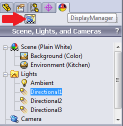
The DisplayManager tab of the FeatureManager can also be used to view or edit the Scene and Lighting currently applied to the model. In the Scene, Lights, and Cameras section, an Ambient and typically a few Directional Lights can be found in the Lights folder, depending on the applied Scene.
Directional Lights can affect the result plot display, especially when rotating the model. As you rotate the model, the Directional Lights may reflect from the faces of the geometry and ‘wash out’ the colors of the result plot. This causes the colors of the result plot to differ from the colors of its color chart. Note the figure below; the left plot is made with directional lights left on, the right is with Directional lights turned off in SolidWorks.
The previous figure is a simple yet clear example of how directional lighting can alter the display of our result plots. The Directional Lights that reflect off the faces of the part make it seem as if the majority of the face is seeing approximately 10MPa of stress based on teal color and the color chart to the right. When the Directional Lights are turned “Off in SolidWorks” we can see the previously hidden details and the stresses are actually fluctuating above and below 10MPa (teal) on the face, between 1MPa (blue) and 27MPa (green).
The easiest way to avoid this issue is to set the Scene to “Ambient Only.” This will disable a majority of the Directional Lights, leaving just the Ambient light. It may be necessary to access the DisplayManager and disable any remaining Directional Lights by right- clicking on the remaining Directional Lights and selecting either “Delete” or “Off in SolidWorks.” Once all of the Directional Lights have been disabled, you can optionally edit the Ambient Light and set the intensity to 1.
By applying “Ambient Only” as the Scene and knowing how to turn off Directional Lighting, users no longer have to worry about the lighting altering the display of their result plots. Share this tip with other Simulation users and help others post-process results with confidence. Remember to check back here often as we will continue to post useful information for all of our products.
Check out more Solidworks tips and tricks on Hawkridge Systems blog: www.hawkridgesys.com/blog/
 Dae Kim is a SolidWorks Elite Applications Engineer at the Hawk Ridge Systems and is certified in many areas of SolidWorks, including Simulation and Flow Simulation, and holds a BSME degree from the University of Washington.


