Using Goal Seek to aid in model design in Solid Edge
By John Pearson, Senior Technical Trainer and Application Specialist, Designfusion
CAD/CAM/CAE CAD Design Fusion sheet metal Solid EdgeAutomate engineering calculations to achieve design goals in Solid Edge.
The Goal Seek command is one of the calculation tools available for engineering problem solving. It is available in the 3D environments and while drawing 2D geometry in a 2D Model sheet, a drawing sheet, a profile, or a sketch.
The Goal Seek command automates engineering calculations, which can be based on dimensioned geometry, to achieve a specific design goal. Goal seeking finds a specific value for a dependent variable (dependent by formula, for example) by adjusting the value of another variable, until it returns the result you want. Goal seeking shows you the effect on the geometry and it will also update the Variable Table with the new value.
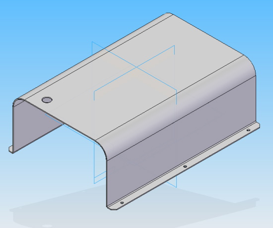
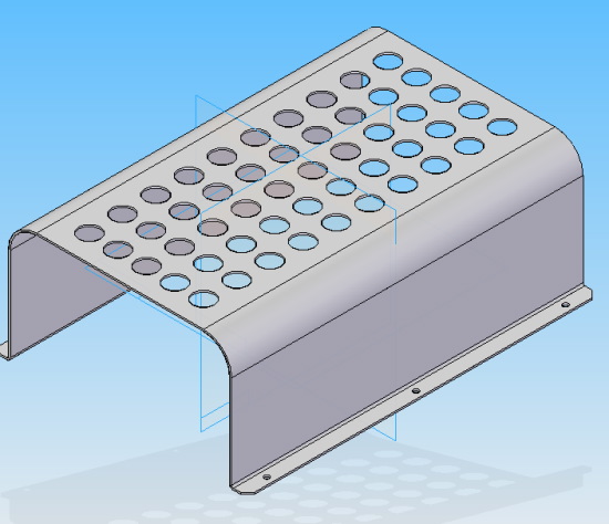
The following is just one example of how to use the Goal Seek command to aid in model creation. This example illustrates how to use the Goal Seek command to help design a sheet metal cover.
Note: For this example, we have to create a hole pattern, on the top of the cover, to allow for air flow. From previous analysis it’s been determined that we need a minimum open area of 6000 mm². To achieve this we will start by creating a circular cutout and rectangular pattern.
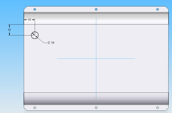
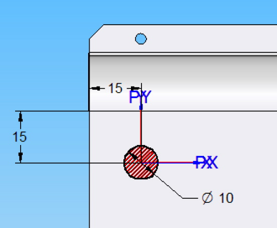
I first create and position a 10 mm radius circle, as shown below, to create our initial cutout.
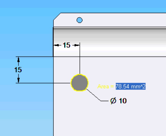
While still in the sketch environment, I select the Area command, from the Inspect tab > Evaluate group.
I then click in the area of the circle.
I accept the Area by selecting the green checkmark on the command bar.
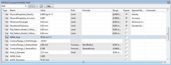
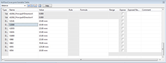
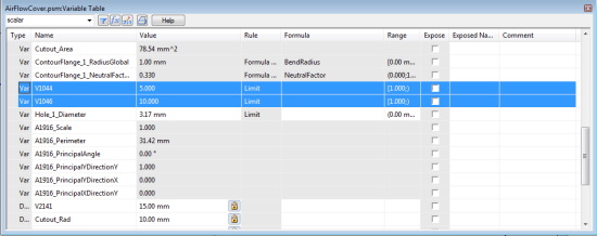
Next I open the Variable table and locate the Area variable and rename it to Cutout_Area.
I also locate the 10 mm variable for the circle radius and rename it to Cutout_Rad.
I then close the Variable table and complete the cutout using the Through All Extent option.
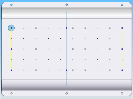
Next, I create a Rectangular Pattern, as shown below, using the Fit option with the following values:
• X: = 10
• Y: = 5
• Width: = 170 mm
• Height: = 65 mm
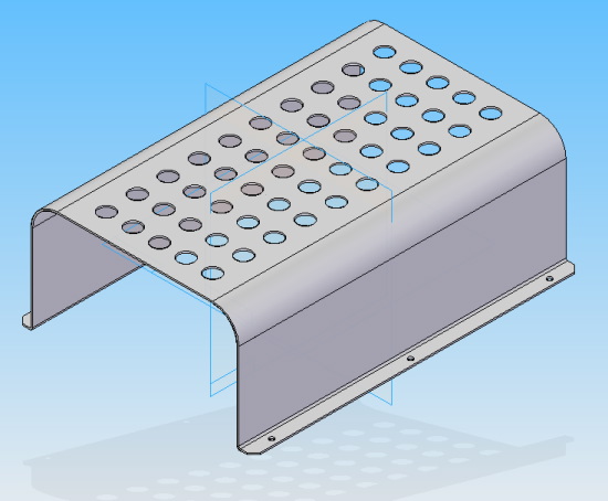
The completed pattern should look like the image below.
To prepare to use Goal Seeking, I need to create some User Variables. First, I find the X and Y occurrence variables and rename them to X_count and Y_count.
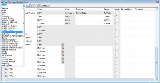
Next, I create a Total_Area variable by clicking in an empty row and selecting the area type, from the pull down scroll, as shown below.
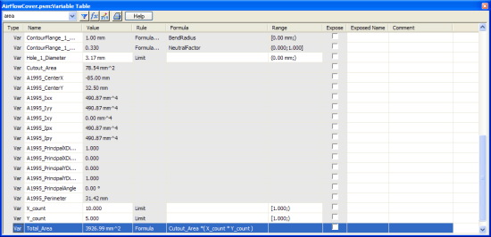
I then type in the name Total_Area and tab over to the Formula column. In the Formula column enter the following formula:
Cutout_Area*(X_count*Y_count)
Note: I have now created a variable to calculate the total open area created by the pattern. I can now use this variable to help adjust the cutout radius to obtain the desired area of 6000 mm².
To do this I select Goal Seek from the Inspect tab > Evaluate group.
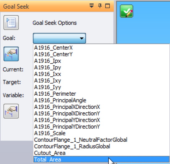
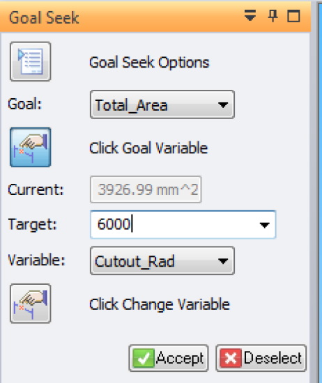
The Goal Seek command bar will appear.
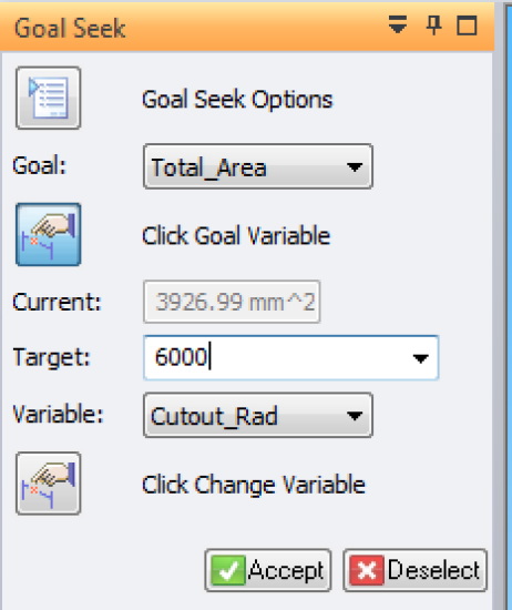
I select the Goal Variable, which is the Total_Area.
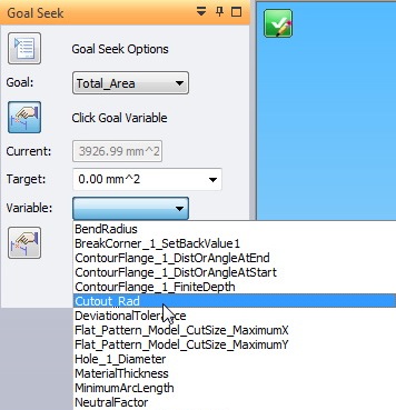
I then select the variable that I will allow to change to obtain the Goal variable, which is the Cutout_Rad.
Now I enter in my target value of 6000 mm². (I just have to enter in 6000)
Note: Goal Seek will now run through a series of iterations, where it will adjust the cutout radius, until it obtains the target value. When it is complete, it will show you the finished model, and post the number of iterations it used and the total elapsed time it took, in the bottom on the Status bar.
If I open the Variable table and view the User Variables, I can see that the radius of the cutout is changed from 10 mm to 12.36 mm, and our total area is now 6000 mm².
Using the Goal Seek command allowed me to determine the optimal radius for my holes without having to do any advanced calculations.
For more practice, try the Solid Edge tutorial on ‘Using Engineering Calculation Tools in Solid Edge.
www.designfusion.com
 John Pearson is a Senior Technical Trainer and Application Specialist at Designfusion. He has over 24 years’ experience in the CAD/CAM industry, is a Certified Adult Trainer and has taught evening CAD courses at colleges in Ontario. He is also a major contributor of articles on the Design Fusion blog.


