
Another Way of Doing MCAD
By Ralph Grabowski
CAD/CAM/CAEHexagon’s BricsCAD diverts from the mainstream by embracing alternative CAD modeling approach.
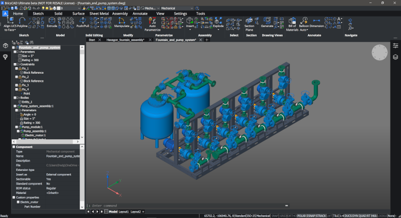
BricsCAD mechanical CAD software designing a system of valves.
(Photo credit: Bricsys)
“Parametric” means the mechanical design software uses formulas to control the sizes and positions of sketches and parts in models. The two are linked such that changing a sketch changes the model – hence the “parametric’ in the PTC company. Each step a designer takes along the way is recorded in a history of actions; editing an element in the history tree also changes related sketches and parts, allowing quick iterations of design ideas, like moving a hole or changing the size of a chamfer, without redrawing the model from scratch.
Nearly every MCAD program subsequently copied Pro/Engineer: Dassault Systemes’ CATIA, Solidworks (the first parametric CAD on Windows), Siemens’ Solid Edge, NX, Autodesk Inventor, you name it. Then parametric modeling migrated to other disciplines, such as architecture and piping.
I should add that parametric design was not invented by PTC; a CAD system that linked 3D models was first developed in the late 1970s in England as 2.5D RUCAPS (Really Universal Computer-Aided Production System) for architectural design, later replaced by 3D Sonata, resurrected as Reflex, and finally purchased by PTC. Although Pro/Reflex failed in the architectural market, PTC found great success at being first-to-market with parametric-based mechanical CAD, albeit on the Unix operating system.
The sketch/parametric/history approach, however, has drawbacks. Making changes to the history could take “forever” with complex models and, in some cases, regenerating new versions of the model unhappily crashed the system.
There is, however, another 3D design approach. It skips 2D sketching and history trees entirely: designers directly draw 3D solid primitives, like boxes and cones, and then use Boolean and other operations to mold the parts into the final shape desired. This is how HP’s Co/Create (bought by, who else, PTC) and Autodesk’s AutoCAD did 3D modeling from day 1.
Today, we call the second approach “direct modeling,” and despite it having a long history, it was resurrected by newer MCAD programs like SpaceClaim (ANSYS), Creo (PTC) and Fusion (Autodesk). The history tree became history.
So, is a third approach to 3D MCAD possible? One day, I envision we might employ a clay-like modeling environment, poking and pulling a shape with our fingers through augmented reality, along with some kind of precision assistance.
BricsCAD Mechanical from Hexagon
Until that kind AR-based modeling becomes normal, if ever, let’s take a look at the different approach to MCAD taken by BricsCAD. It combines parametrics with direct modeling, leaves out the history tree and makes sketches optional.
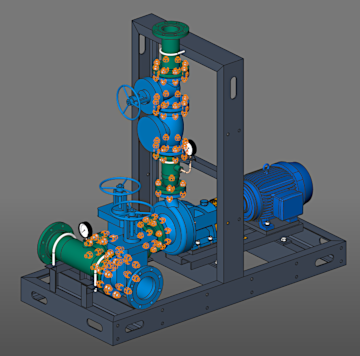
With BricsCAD’s smart search and replace function, 42 bolts can be added at once.
(Photo credit: Bricsys)
There was, at the time, speculation Bricsys might adopt the old Architecturals code to the new BricsCAD, but the company demurred, instead developing its own 3D modeling system based on the ACIS modeling kernel from Dassault Systemes’ Spatial and a 3D design system developed by programmers at LEDAS in Russia.
The system combined parametrics with feature recognition and direct modeling/editing, and, more recently, artificial intelligence. It was good enough that Bricsys bought the intellectual property from LEDAS, as well as hired some of its staff. In a twist, however, BricsCAD employed LEDAS’ 2D and 3D parametric system, not Spatial’s, making it incompatible in that area with other design systems.
The workflow looks like this. First, you import a 3D model into BricsCAD Mechanical from another MCAD program with a separate, extra-cost option called “Communicator,” which is the InterOp translator licensed from Spatial. At this point, the imported model is dumb, so you apply BricsCAD’s features recognition, which add smarts (i.e. parametrics) to the model. You then change the model with BricsCAD’s direct editing functions.
If this doesn’t seem new to you, that’s because MCAD competitors mimicked the workflow; others are scrambling to catch up in the area of automatic feature recognition. BricsCAD subsequently added semi-automated search-and-replace, in which you specify a feature (say a hole) and the block with which to replace it (like a drill tap), and BricsCAD finds all occurrences.
BricsCAD has a number of automation techniques that it calls A.I. One is “propagation,” which searches for likely elements like joints and then adds connections. Another is “blockification,” which looks for identical instances of groups of entities and then converts them to blocks. A third is “optimization,” which finds lines at slight angles and straightens them.
There are a couple benefits to applying these techniques to drawings. One is that replacing repeated details (like gussets) with blocks greatly reduces a file’s size.
The other, more important, benefit is hyper-fast detailing – think specifying details of joints (typically made of several bolts, cutouts and stiffeners) between dozens of columns and beams in structures.
BricsCAD BIM uses the same import/recognize/edit system to turn dumb IFC files into smart BIM ones. “Bimification” for instance defines vertical and horizontal slabs as walls and floors automatically.
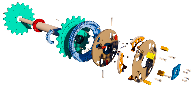
In BricsCAD, exploded assemblies can be bi-directionally linked to BOMs (bills of materials)
(Photo credit: Bricsys)
In another divergence from mainstream MCAD, BricsCAD stores its design data in DWG files, the same used by AutoCAD. The DWG format is flexible enough to store all kinds of data not defined by Autodesk. This makes drawings made with BricsCAD Mechanical compatible with BricsCAD BIM, something Autodesk cannot offer its mechanical and architectural customers, ironically enough.
Nevertheless, Bricsys had to come up with some workarounds. For instance, DWG does not support assemblies, and so BricsCAD connects parts stored in xrefs with 3D constraints. Other data is stored in other formats for optimization reasons, such as point clouds in BPT (Bricsys Point Tree) files.
Depending on the vertical edition, BricsCAD has built-in sheet metal design, civil terrain and roadway design, MEP (mechanical, engineering, plumbing), BIM (building information modeling), and kinematic analysis – all stored in DWG files.
A few years ago, the company released a free 3D modeling program, Shape, positioning it as a pre-design program, like SketchUp. Unlike SketchUp, it works with 3D solids. Drawings made with Shape are, however, limited to being imported into BricsCAD.
Sweden’s Hexagon bought Belgium’s Bricsys a few years ago, after being impressed how well BricsCAD replaced AutoCAD in its CADWorx plant design software.
The good news is that, so far, Hexagon seems to have left BricsCAD development alone, meaning it continues at its usual frenetic pace. As happens with acquisitions, some Bricsys executives eventually left Hexagon to form a new company, Qonic, which promises to create a new way of working with very large IFC and BIM files.
Despite Bricsys doing a lot of deep thinking on how CAD ought to operate, it continues to be a small company, with only 300,000 users, a number that hasn’t seemed to change over the years.
It can never replace Pro/Engineer or Solidworks, so it places the emphasis on being different: a direct editor for MCAD systems incapable of direct editing at a third the cost, along with a dash of A.I. and everything stored in DWG files.
www.bricsys.com
Ralph Grabowski writes on the CAD industry on his WorldCAD Access blog. He has authored numerous articles and books on CAD, Visio and other design software applications.